Textile fabric rapid carding equipment and working method thereof

A technology for textile fabrics and working methods, applied in spray/jet textile material processing, textile and papermaking, fabric surface trimming, etc. Increase efficiency, increase the effect of adsorption effect

Inactive Publication Date: 2021-01-15
沈足金
View PDF7 Cites 2 Cited by
  • Summary
  • Abstract
  • Description
  • Claims
  • Application Information

AI Technical Summary

Problems solved by technology

[0005] In order to make up for the deficiencies of the existing technology, the existing technology uses the bristles to comb the remaining fluff on the surface of the cloth with the rotation of the cleaning roller, and then uses the negative pressure device to pump air from the round tube and the cleaning roller, and then absorbs the cloth through the negative pressure hole fluff and dust, but the negative pressure hole is easy to block after absorbing fluff and dust for a long time, reducing the carding effect of fluff and dust on the cloth. A kind of textile fabric rapid carding equipment and working method proposed by the present invention

Method used


Image

  • Textile fabric rapid carding equipment and working method thereof
  • Textile fabric rapid carding equipment and working method thereof
  • Textile fabric rapid carding equipment and working method thereof

Examples


Embodiment approach

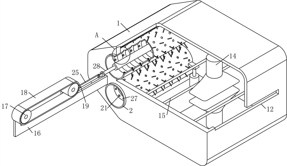
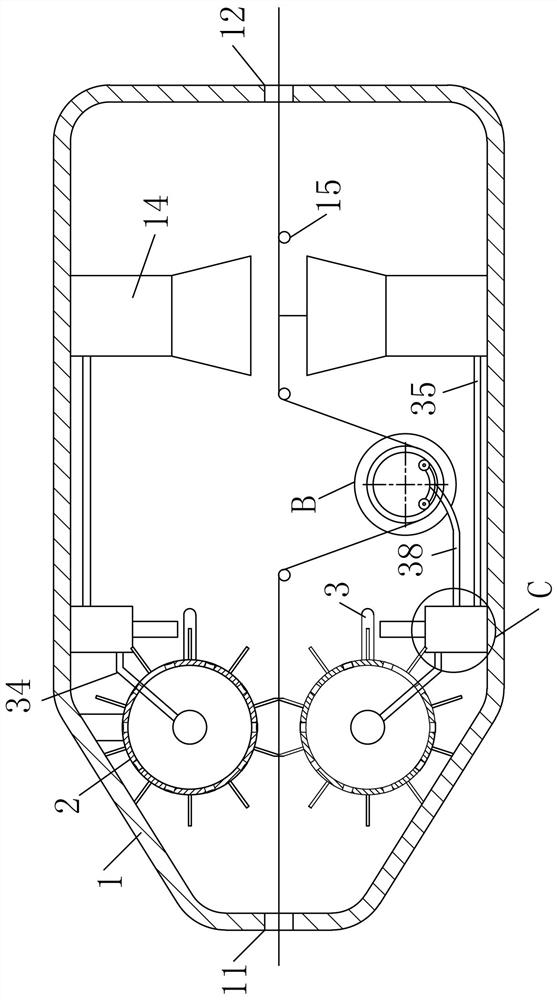
[0030] As an embodiment of the present invention, the negative pressure device includes a pressure rod 3, which is fixedly connected to the outer periphery of the cleaning roller 2; a cylinder 31 is fixedly connected to the position corresponding to the pressure rod 3 in the body 1, and the inside of the cylinder 31 A piston rod 32 and a piston rod 33 are slidably connected; a spring is arranged between the piston rod 32 and the bottom of the cylinder 31; A one-way valve is provided; the rodless cavity of the cylinder 31 communicates with the ironing unit 14 through the No. 2 pipe 35, and a heating ring 36 is arranged on the outer periphery of the rodless cavity of the cylinder 31, and the heating ring 36 is connected to a power supply through a controller; The pressure rod 3 squeezes the piston rod 33 when it rotates with the cleaning roller 2; the pressure rod 3 is driven by the cleaning roller 2 to rotate continuously, so that the pressure plate moves to the corresponding po...


PUM


Abstract

The invention belongs to the technical field of textile equipment, and particularly relates to textile fabric rapid carding equipment and a working method thereof. The textile fabric rapid carding equipment comprises a machine body; a feeding hole and a discharging hole are formed in the two sides of the machine body correspondingly; a pair of circular pipes are rotatably connected to the side, close to the feeding hole, in the machine body through a bracket; one end of each circular pipe is fixedly connected with a hollow clearing roller, and the other ends of the circular pipes communicate with negative pressure devices; and a group of negative pressure holes are uniformly distributed at the periphery of each clearing roller, and a group of bristles are circumferentially and uniformly distributed at the position, between the adjacent negative pressure holes, of each clearing roller. The ends, away from the circular pipes, of the clearing rollers penetrate through the machine body andextend out of the machine body, and pushing rods are arranged in the clearing rollers; brush plates are arranged at the ends, located in the clearing rollers, of the pushing rods; supporting seats are fixedly connected to the position, corresponding to the clearing rollers, of the machine body, and a pair of rollers is arranged on each supporting seat; and a conveying belt is arranged between theevery two rollers in a sleeving mode, one side of each conveying belt is fixedly connected with a rotating pin, and the rotating pins are hinged to the pushing rod through connecting rods. Accordingto the textile fabric rapid carding equipment, the brush plates are driven by the conveying belts to continuously scrape the inner walls of the clearing rollers, and the carding efficiency of cloth isimproved.

Description

technical field [0001] The invention belongs to the technical field of textile equipment, in particular to a rapid carding equipment and working method for textile fabrics. Background technique [0002] Textile fabrics, also known as knitted fabrics, are divided into two types according to weaving methods: weft-knitted fabrics and warp-knitted fabrics. Weft-knitted fabrics are often made of low-elastic polyester yarn or special-shaped polyester yarn, nylon yarn, cotton yarn, wool yarn, etc. Circle weaves, etc., are woven on various weft knitting machines. After the cloth is produced, some adsorbents such as floating hair and dust will be adsorbed on it. [0003] There are also some technical solutions for textile equipment in the prior art. For example, a Chinese patent with application number 2020102649765 discloses a rapid carding equipment for textile fabrics, including a body whose inner wall is rotatably connected to two rotating rollers. , the middle parts of the tw...

Claims


Application Information

Patent Timeline
Patent Type & Authority Applications(China)
IPC IPC(8): D06G1/00D06B1/02D06C15/00B08B9/00
CPCB08B9/00D06B1/02D06C15/00D06G1/00
Inventor 沈足金
Owner 沈足金
Why Eureka
Try Eureka