
Fan blade device for brushless fan

A technology of brushless motors and fan blades, which is applied to the components of pumping devices for elastic fluids, pump devices, mechanical equipment, etc., which can solve the unfavorable service life of brushless motor shafts and reduce the service life of brushless motor shafts , Increase the energy consumption of brushless fans and other issues, to achieve the effect of ensuring air delivery efficiency, improving service life, and low mold precision requirements

Active Publication Date: 2022-05-03
湖南伟力汽车零部件有限公司
View PDF0 Cites 0 Cited by
  • Summary
  • Abstract
  • Description
  • Claims
  • Application Information

AI Technical Summary

Problems solved by technology

The blades of the existing brushless fans usually use straight blades, resulting in a small conveying wind force, and there will be wind loss at the edge of the blades, thereby increasing the energy consumption of the brushless fan and reducing the air conveying efficiency
Moreover, when the existing fan blades are rotated, due to factors such as processing accuracy, momentum imbalance, and working environment, the entire fan blade will perform torsional vibration on the surface where the central axis of the brushless motor is located, and the brushless fan will generate relatively high vibration. Large vibration, and when the fan blades twist, it will exert bending stress on the shaft of the brushless motor, thereby reducing the service life of the shaft of the brushless motor. In addition, the shaft of the brushless motor is greatly affected by the inertia at the moment of starting the fan blade The torsional stress effect of the brushless motor is not conducive to improving the service life of the shaft of the brushless motor. In view of this, we propose a fan blade device for a brushless fan

Method used


Image

  • Fan blade device for brushless fan
  • Fan blade device for brushless fan
  • Fan blade device for brushless fan

Examples


Embodiment Construction

[0022] The following will clearly and completely describe the technical solutions in the embodiments of the present invention with reference to the accompanying drawings in the embodiments of the present invention. Obviously, the described embodiments are only some, not all, embodiments of the present invention. Based on the embodiments of the present invention, all other embodiments obtained by persons of ordinary skill in the art without creative efforts fall within the protection scope of the present invention.

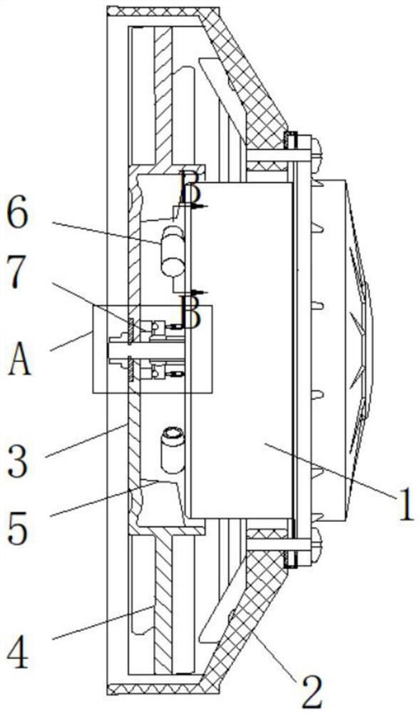
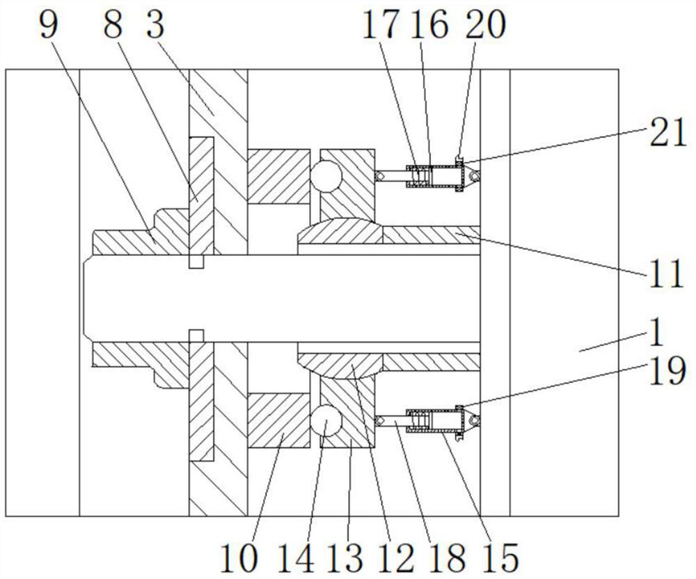
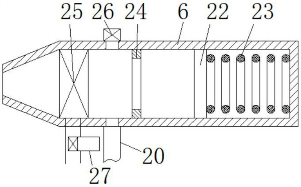
[0023] see Figure 1 to Figure 5 , the present invention provides a technical solution: a fan blade device for a brushless fan, including a fan blade assembly arranged on the shaft of a brushless motor 1, a net cover 2 is fixed on the shell of the brushless motor 1, and the fan The blade assembly is arranged on the inner side of the grille 2. The blade assembly includes a drum 3 with one end open. The rotating shaft of the brushless motor 1 runs through the center ...


PUM


Abstract

The invention relates to the field of brushless fans, in particular to a fan blade device for a brushless fan, which includes a fan blade assembly arranged on the shaft of a brushless motor. There is a buffer mechanism for suppressing the torsional vibration of the drum between the casing of the brushless motor and the casing of the brushless motor. There are a number of paddles fixed on the inner peripheral wall of the drum. The buffer mechanism passes through the air pipe to the storage Air is conveyed inside the air cylinder to increase the internal pressure of the air storage cylinder. The air storage cylinder can generate aerodynamic thrust on the paddle to make the paddle drive the rotor to rotate. The fan blade assembly also includes a ring cylinder. A plurality of vanes are arranged between the outer wall of the cylinder and the inner wall of the annular cylinder. The fan blade device used for the brushless fan improves and guarantees high-efficiency air delivery efficiency, improves the service life of the rotating shaft of the brushless motor, and reduces energy consumption.

Description

technical field [0001] The invention relates to the field of brushless fans, in particular to a fan blade device for a brushless fan. Background technique [0002] The brushless fan uses a brushless motor as the driving element and drives the fan blades to rotate, so as to perform work on the air for air delivery. The blades of the existing brushless fan usually use straight blades, which results in a small conveying wind force, and there will be wind loss at the edge of the blade, thereby increasing the energy consumption of the brushless fan and reducing the air conveying efficiency. Moreover, when the existing fan blades are rotated, due to factors such as processing accuracy, momentum imbalance, and working environment, the entire fan blade will perform torsional vibration on the surface where the central axis of the brushless motor is located, and the brushless fan will generate relatively high vibration. Large vibration, and when the fan blades twist, it will exert be...

Claims


Application Information

Patent Timeline
Patent Type & Authority Patents(China)
IPC IPC(8): F04D25/08F04D29/58
CPCF04D25/08F04D25/0606F04D29/5806F04D29/582
Inventor 杨浩
Owner 湖南伟力汽车零部件有限公司
Learn More