Aircraft pylon grid generation and projection method and device, equipment and storage medium

A technology for grid generation and projection position, which is applied in computer-aided design, design optimization/simulation, and special data processing applications, etc. It can solve problems such as grid distortion, manual processing, and long time for grid establishment, and achieve enhanced accuracy performance, reduce impact, and avoid effects with gaps

Pending Publication Date: 2021-01-15
BEIJING AERONAUTIC SCI & TECH RES INST OF COMAC +1
View PDF0 Cites 2 Cited by
  • Summary
  • Abstract
  • Description
  • Claims
  • Application Information

AI Technical Summary

Problems solved by technology

[0002] For the overall aerodynamic design of the aircraft, a basic element is the fast and accurate analysis of the flow field characteristics of various configurations of the aircraft. With the continuous development of computational fluid dynamics technology, many mature commercial software have been widely used in aircraft design In engineering practice, most software needs third-party grid generation software to build calculation grids during process analysis, and the time to build grids is often longer
In addition, in engineering applications, it is often necessary to deform the mesh, and the deformation of the mesh created by the third-party software often requires manual processing, which is complicated to operate and has a low degree of automation.
In addition, during the deformation process of the grid, the phenomenon of grid distortion and grid scissors will be caused, which will seriously affect the calculation accuracy of the flow field.
[0003] For aircraft pylon components, which are generally connected to the fuselage, wing, nacelle and other components, the geometric complexity of aircraft pylon components is high, and it is more difficult to automatically generate high-quality structured body-fitted meshes. Through third-party Grid generation software is extremely difficult to generate, and for automatic grid generation technology, nested grid calculations are often used for aircraft components with high geometric complexity, that is, the entire flow field is divided into sub-regions, and each sub-region is based on the geometric characteristics of aircraft components The calculation grid is generated independently, and the establishment of the boundary surface of the sub-area grid is not affected by other sub-area grids. Each sub-area is relatively independent, but there is a gap in the established grid when two different geometric components are connected. , which has an impact on the analysis of the flow field characteristics of the aircraft pylon grid components

Method used


Image

  • Aircraft pylon grid generation and projection method and device, equipment and storage medium
  • Aircraft pylon grid generation and projection method and device, equipment and storage medium
  • Aircraft pylon grid generation and projection method and device, equipment and storage medium

Examples


Embodiment 1

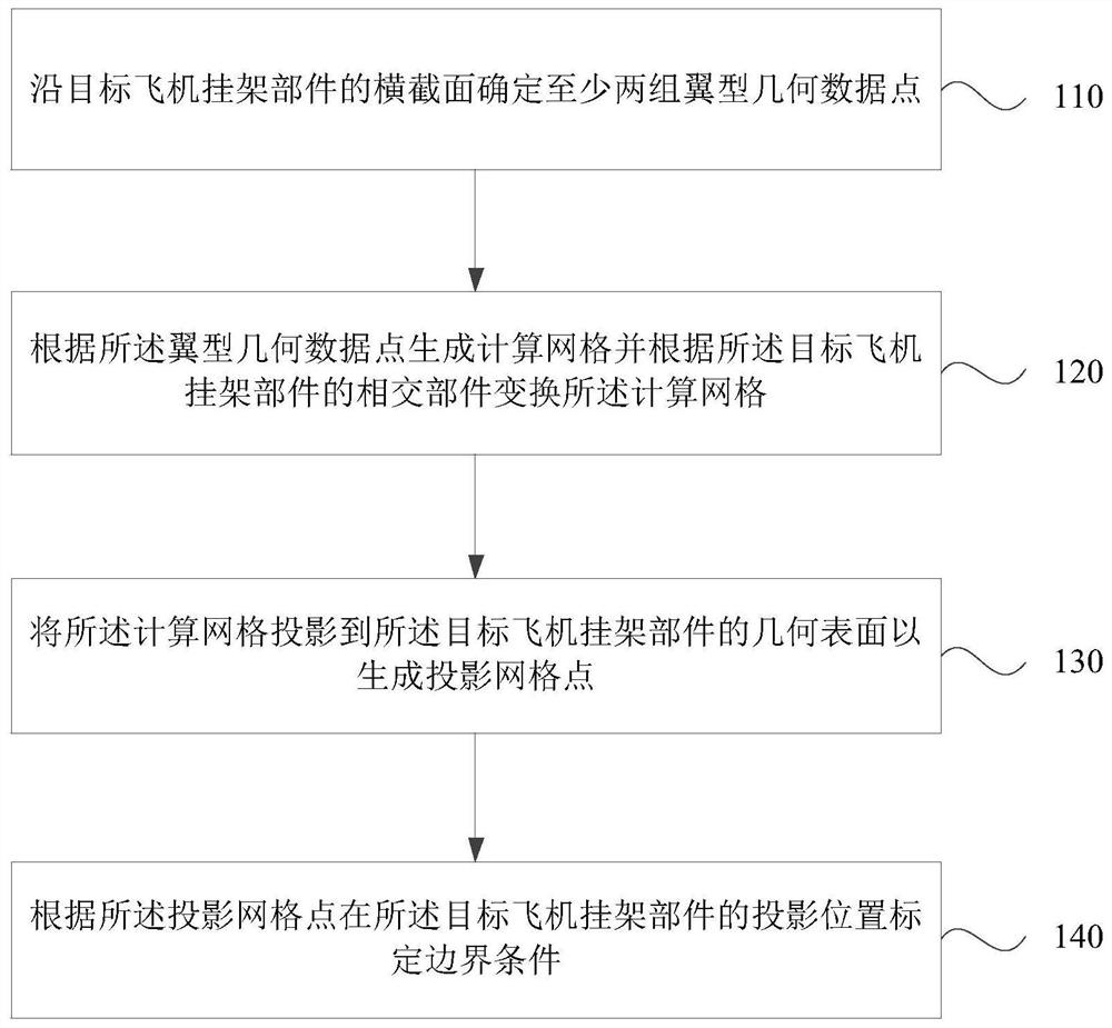
[0039] figure 1 It is a flow chart of an aircraft pylon grid generation and projection method provided by Embodiment 1 of the present invention. This embodiment is applicable to the situation where aircraft pylon components automatically generate calculation grids. This method can be composed of aircraft pylon grids generating and projecting means, which can be realized by means of hardware and / or software, see figure 1 The aircraft pylon grid generation and projection method provided by the embodiment of the present invention specifically includes the following steps:

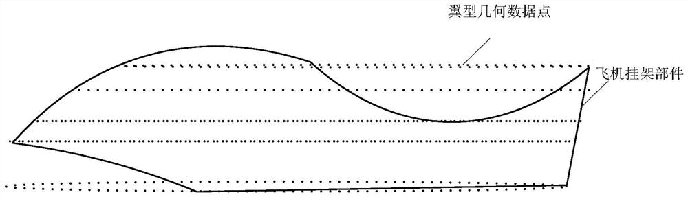
[0040] Step 110, determine at least two groups of airfoil geometry data points along the cross-section of the target aircraft pylon component.

[0041] Wherein, the target aircraft pylon component may have a complex geometric shape, and the target aircraft pylon component may intersect with the fuselage component, the nacelle component, the wing component, and the like. The airfoil geometric data point may b...

Embodiment 2

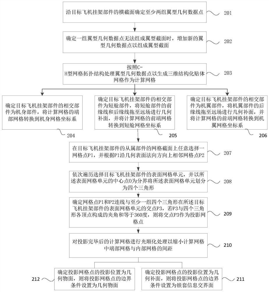
[0054] figure 2 It is a flowchart of an aircraft pylon grid generation and projection method provided by Embodiment 2 of the present invention. The embodiment of the present invention is based on the embodiment of the above invention. See figure 2 , the method provided in the embodiment of the present invention specifically includes the following steps:

[0055] Step 201, determine at least two groups of airfoil geometry data points along the cross-section of the target aircraft pylon component.

[0056] Step 202, when it is determined that a set of airfoil geometric data points cannot form the airfoil section, add new airfoil geometric data points to form the airfoil section.

[0057] In the embodiment of the present invention, since a group of airfoil geometric data points obtained on the cross section of the target aircraft pylon part may not be able to form an airfoil, a group of airfoil geometric data points can be supplemented. A group of airfoil geometric data point...

Embodiment 3

[0097] Figure 11 It is a schematic structural diagram of an aircraft pylon grid generation and projection device provided in Embodiment 3 of the present invention, which can execute the aircraft pylon grid generation and projection method provided in any embodiment of the present invention, and has corresponding functional modules for executing the method and beneficial effects. The device can be implemented by software and / or hardware, and specifically includes: a data acquisition module 301 , a grid transformation module 302 , a grid projection module 303 and a boundary condition module 304 .

[0098] The data acquisition module 301 is configured to determine at least two groups of airfoil geometry data points along the cross section of the target aircraft pylon component.

[0099] A grid transformation module 302, configured to generate a calculation grid according to the airfoil geometry data points and transform the calculation grid according to the intersecting compone...


PUM


Abstract

The invention discloses an aircraft pylon grid generation and projection method and device, equipment and a storage medium, and the method comprises the steps: determining at least two groups of airfoil profile geometric data points along the cross section of a target aircraft pylon part; generating a calculation grid according to the airfoil profile geometric data points, and transforming the calculation grid according to the intersection components of the target aircraft pylon component; projecting the computational grid to a geometric surface of the target aircraft pylon component to generate projection grid points; and calibrating boundary conditions according to the projection positions of the projection grid points on the target aircraft hanger component. According to the embodimentof the invention, the method and device achieve the automatic generation of the calculation grid through a plurality of groups of airfoil profile geometric data points, avoid the gaps between grids ofdifferent parts according to the intersected parts and the projection grid, improve the generation quality of the calculation grid, and improve the accuracy of flow field characteristic analysis.

Description

technical field [0001] Embodiments of the present invention relate to the technical field of computer applications, and in particular to a method, device, device and storage medium for generating and projecting aircraft pylon grids. Background technique [0002] For the overall aerodynamic design of the aircraft, a basic element is the fast and accurate analysis of the flow field characteristics of various configurations of the aircraft. With the continuous development of computational fluid dynamics technology, many mature commercial software have been widely used in aircraft design In engineering practice, most software needs third-party grid generation software to build calculation grids during process analysis, and the time to build grids is often long. In addition, in engineering applications, it is often necessary to deform the grid, and the deformation of the grid created by the third-party software often requires manual processing, which is complicated and has a low ...

Claims


Application Information

Patent Timeline
Patent Type & Authority Applications(China)
IPC IPC(8): G06F30/15G06F30/20G06F113/28
CPCG06F30/15G06F30/20G06F2113/28
Inventor 孙明哲李政德林榕婷吴东润
Owner BEIJING AERONAUTIC SCI & TECH RES INST OF COMAC
Why Eureka
Try Eureka