Tdr measuring apparatus for determining the dielectric constant

A technology of dielectric constant and measuring equipment, which is applied in the field of TDR measuring equipment, can solve the problem of short TDR electromagnetic wave propagation time, and achieve the effect of eliminating the distance requirement

Pending Publication Date: 2021-01-15
IMKO MICROMODULTECHN
View PDF8 Cites 2 Cited by
  • Summary
  • Abstract
  • Description
  • Claims
  • Application Information

AI Technical Summary

Problems solved by technology

[0008] The challenge of TDR measurement is that the propagation time of the electromagnetic wave on the probe is very short

Method used


Image

  • Tdr measuring apparatus for determining the dielectric constant
  • Tdr measuring apparatus for determining the dielectric constant
  • Tdr measuring apparatus for determining the dielectric constant

Examples


Embodiment Construction

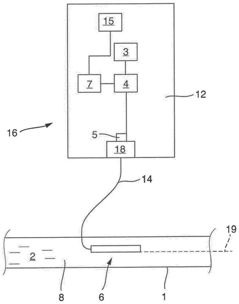
[0041] figure 1 A schematic representation of a first embodiment of a TDR measuring device according to the invention for determining at least the dielectric constant of a medium 2 passing through a pipeline 1 and optionally deriving it in a non-contact or non-invasive manner is shown properties of the medium, and / or the TDR measuring device is used to detect the state change of the pipeline 1 through which the medium 2 flows. The TDR measuring device consists of a sensor or measuring probe 6 and measuring electronics 16 . In the case shown, the two components 6 , 16 are spaced apart from one another and connected to one another by a measuring line 14 . The measuring line 14 is preferably a coaxial cable.

[0042] The electronic components of the measurement electronics 16 are arranged on the circuit board 12 : the signal generation electronics 3 , the sending and / or receiving electronics 4 , the coupling / decoupling device 5 and the control / evaluation electronics 7 . Signa...


PUM


Abstract

The invention relates to a TDR measuring apparatus for determining at least the dielectric constant and material properties possibly derived therefrom, in particular the moisture and / or the conductivity, of a medium (2) flowing through a pipeline (1), having signal generation electronics (3) which generate TDR measurement signals, transmitting and / or receiving electronics (4) which emit and / or receive the TDR measurement signals, a coupling-in / coupling-out apparatus (5) which couples the TDR measurement signals into an electrical conductive measuring probe (6) of a predefined length (L) and couples said signals out of the measuring probe (6), and control / evaluation electronics (7) which use the propagation time of the TDR measurement signals on the measuring probe (6) to determine at leastthe dielectric constant and material properties possibly derived therefrom, in particular the moisture and / or the conductivity, wherein the measuring probe(6) is arranged in an electrically insulatedmanner outside the interior (8) of the pipeline (1) through which the medium (2) flows, or wherein the measuring probe (6) is placed in the pipeline (1) in such a manner that the outer surface of themeasuring probe (6) facing the medium (2) terminates in a manner flush with the inner surface of the pipeline (1) facing the medium (2), and is configured such that the propagation time and / or the amplitude of the measurement signals on the measuring probe (6) is / are dependent on the dielectric constant of the medium (2) flowing through the pipeline (1).

Description

technical field [0001] The invention relates to a TDR measuring device for determining the permittivity of a medium passing through a pipeline and / or material properties derived from said permittivity, in particular water content and / or electrical conductivity. It goes without saying that the conduit may be any wire suitable for carrying the medium. Therefore, it can be a closed line or a channel-shaped line. Background technique [0002] The dielectric TDR measurement principle has been used in many industrial applications to determine the water content of media. The dielectric constant (DC) of the material is measured via a radio frequency electromagnetic field which penetrates the material to be measured. The dielectric constant of water has a value of 80 at 20° C., and is therefore very different from that of solids, which have a DC value of 3 to 30, depending on the material. With this strong dielectric contrast, the dielectric constant can thus be used as a paramete...

Claims


Application Information

Patent Timeline
Patent Type & Authority Applications(China)
IPC IPC(8): G01N27/22
CPCG01N27/221G01N27/223G01R27/2647G01R27/2658G01R27/2676
Inventor 蒂莫·卡梅克格德·格里奇斯蒂芬·罗尔夫
Owner IMKO MICROMODULTECHN
Why Eureka
Try Eureka