
Atomizer cleaning tank with automatic cleaning function

A technology of atomizer and cleaning tank, applied in the direction of spray device, etc., can solve the problem of inconvenient cleaning of the atomizing head, and achieve the effects of convenient automatic cleaning, labor reduction, and low cleaning cost

Pending Publication Date: 2021-01-19
滕州图西格斯环保设备有限公司
View PDF0 Cites 0 Cited by
  • Summary
  • Abstract
  • Description
  • Claims
  • Application Information

AI Technical Summary

Problems solved by technology

[0005] Aiming at the deficiencies of the prior art, the present invention provides an atomizer cleaning tank with an automatic cleaning function, which solves the problem of inconvenient cleaning of stubborn stains deposited on the atomizing head

Method used


Image

  • Atomizer cleaning tank with automatic cleaning function
  • Atomizer cleaning tank with automatic cleaning function
  • Atomizer cleaning tank with automatic cleaning function

Examples


no. 1 example

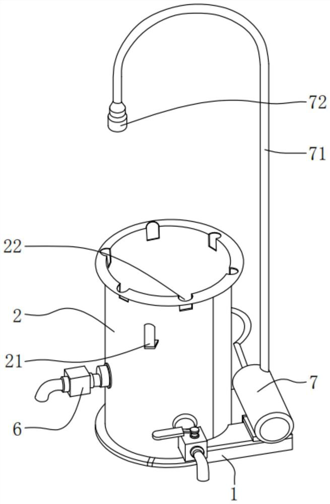
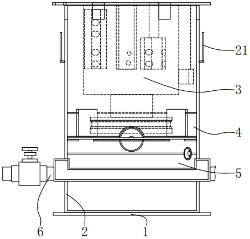
[0031] see Figure 1-2 , the embodiment of the present invention provides a technical solution: an atomizer cleaning tank with automatic cleaning function includes a base 1, a tank body 2 is connected to the top of the base 1, and the outer surface of the tank body 2 is provided with Cable support 21, the top of the tank body 2 is provided with an atomizer positioning port 22, the inside of the tank body 2 is respectively provided with a cleaning cavity 3 and an underflow cavity 5, the cleaning cavity 3 and An overflow port 4 is arranged between the lower overflow chambers 5, the input end of the overflow port 4 communicates with the inside of the cleaning chamber 3, and the output end of the overflow port 4 communicates with the interior of the cleaning chamber 3. The interior of the underflow cavity 5 is connected to each other, the output end of the underflow cavity 5 is provided with a manual acid discharge port 6, and the top of the base 1 is fixedly connected with an aci...

no. 2 example

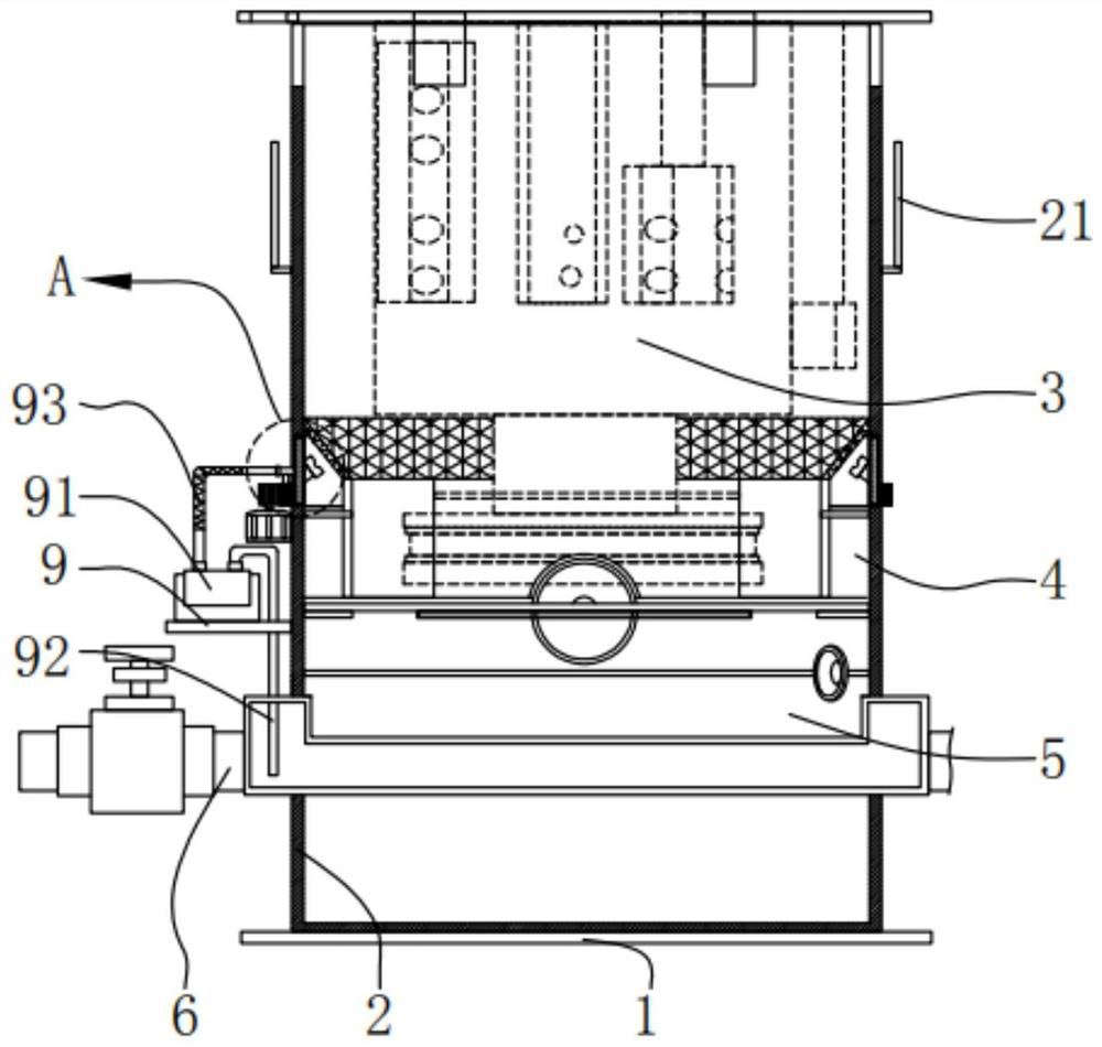
[0046] see image 3 and Figure 4 , based on the atomizer cleaning tank with automatic cleaning function provided in the first embodiment of the present application, the second embodiment of the present application proposes another atomizer cleaning tank with automatic cleaning function. The second embodiment is only a preferred mode of the first embodiment, and the implementation of the second embodiment will not affect the independent implementation of the first embodiment. Specifically, the difference between the atomizer cleaning tank with automatic cleaning function provided in the second embodiment of the present application is that the atomizer cleaning tank with automatic cleaning function also includes a shielding screen 8, the The shielding screen 8 is fixed on the top of the overflow port 4, and the shielding screen 8 is arranged obliquely with an inclination angle of 45°. The outer surface of the tank body 2 is provided with a linkage sliding hole 23, and the link...


PUM


Abstract

The invention discloses an atomizer cleaning tank with the automatic cleaning function. The tank comprises a base, a tank body is connected to the top of the base, a cable support is arranged on the outer surface of the tank body, an atomizer positioning opening is formed at the top of the tank body, and a cleaning cavity and a lower overflow cavity are formed in the tank body; and an overflow port is formed between the cleaning cavity and the lower overflow cavity. The invention relates to the technical field of atomizer cleaning tanks. According to the atomizer cleaning tank with the automatic cleaning function, a weak acid solution in the cleaning cavity submerges an atomizing head and is lower than the top of an overflow port, the atomizing head can be conveniently cleaned through theweak acid solution, dirt on the surface of the atomizing head is cleaned through weak acid, the cleaning cost is reduced to the minimum, the labor force of manual operation is reduced, and convenientautomatic cleaning is achieved. Acid is protected from keeping out of an atomizer, the service life of an atomizing head is prolonged through sufficient cleaning treatment, the operation cost is reduced, and the automation degree is improved.

Description

technical field [0001] The invention relates to the technical field of atomizer cleaning tanks, in particular to an atomizer cleaning tank with an automatic cleaning function. Background technique [0002] Waste incineration power plants mostly use semi-dry desulfurization and dust removal systems. In this system, the atomizer is the core component. The atomizer is affected by the quality of the lime slurry used and the operating conditions, which will cause the atomization wheel or even atomization. If the atomizer is blocked by sticky slurry, it will directly affect the quality of waste incineration exhaust gas or directly damage the atomizer. [0003] In the existing technology, the atomizer is a high-end technical product, which is expensive, and even a small damage will cause great economic losses. The atomizer uses a program to perform regular self-cleaning actions in the volute cavity, which cannot completely solve the fog Stubborn stains deposited by the head during...

Claims


Application Information

Patent Timeline
Patent Type & Authority Applications(China)
IPC IPC(8): B05B15/555
CPCB05B15/555
Inventor 杨开宇
Owner 滕州图西格斯环保设备有限公司
Learn More