Eureka AIR delivers breakthrough ideas for toughest innovation challenges, trusted by R&D personnel around the world.

Ultrasonic cleaning device

A cleaning device and ultrasonic technology, applied in the directions of drying gas arrangement, cleaning methods and utensils, cleaning methods using liquids, etc., can solve the problems of unfiltered, dirty cleaning liquid, unable to achieve continuous and efficient cleaning of workpieces, etc. Easy to clean and save labor

Active Publication Date: 2021-01-19
LEELOOL PURIFIER TECHNOLOGY (DONGGUAN) LIMITED COMPANY
View PDF7 Cites 1 Cited by
  • Summary
  • Abstract
  • Description
  • Claims
  • Application Information

AI Technical Summary

Problems solved by technology

[0003] However, because the existing cleaning machine does not have a water circulation device and a temperature control device, after the cleaning parts are ultrasonically cleaned in the cleaning tank, the cleaning liquid still stays in the cleaning tank, and the impurities or oil stains have not been filtered, so the impurities or oil stains cannot be removed. After a certain number of workpieces are finished, the cleaning liquid in the cleaning tank will become dirty. When the cleaning liquid contains a lot of impurities, it will affect the washing effect, so the cleaning liquid should be replaced frequently, resulting in waste of cleaning liquid. When the cleaning liquid is directly mixed with dirt When discharged, the purpose of continuous and efficient cleaning of the workpiece cannot be achieved, and it will cause environmental pollution

Method used


Image

  • Ultrasonic cleaning device
  • Ultrasonic cleaning device
  • Ultrasonic cleaning device

Examples


Embodiment Construction

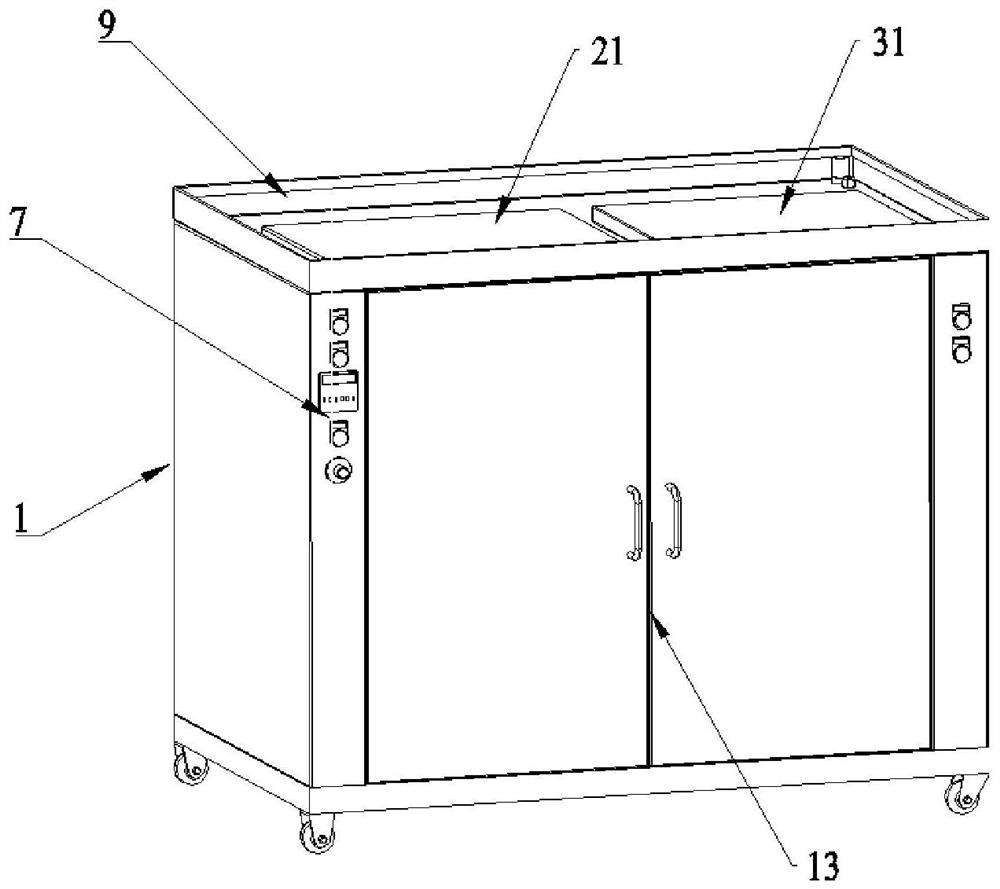
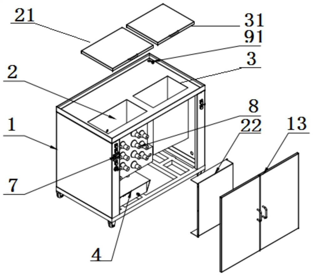
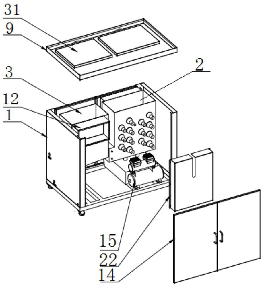
[0025] For the convenience of those skilled in the art to understand, below in conjunction with embodiment and appended Figure 1-8 To further illustrate the present invention, the content mentioned in the embodiment is not to limit the present invention.

[0026] See Figure 1-8 , an ultrasonic cleaning device, comprising a machine base 1, a cleaning tank 2, a drying tank 3, an ultrasonic generator 4, a water circulation system 5, an automatic heating mechanism 6, a numerical control component 7, an air compressor 15 and several ultrasonic vibrators 8, The water circulation system 5 includes a water inlet pipe 51, a circulating water pump 52, a first water outlet pipe 54, a filter 55, a second water outlet pipe 56, a purifier 57, a metal bellows 58 and a third water outlet pipe 59 connected in sequence; The cleaning tank 2 is set in the base 1, the drying tank 3 is set in the base 1 and is located on one side of the cleaning tank 2, and the ultrasonic generator 4 is set in t...


PUM


Abstract

The invention relates to the technical field of mechanical equipment cleaning, and specifically relates to an ultrasonic cleaning device. The ultrasonic cleaning device comprises a machine seat, a cleaning groove, a drying groove, an ultrasonic generator, a water circulation system, an automatic heating mechanism, a numerical control assembly, an air compressor and a plurality of ultrasonic vibrators, wherein the cleaning groove is formed in the machine seat; the drying groove is formed in the machine seat; the ultrasonic generator is arranged on the machine seat, located below the cleaning groove and connected with the numerical control assembly; the ultrasonic vibrators are arranged on the outer side wall and the bottom surface of the cleaning groove and connected with the ultrasonic generator; the automatic heating mechanism is arranged in the cleaning groove and connected with the numerical control assembly; the numerical control assembly is arranged on the side wall of the machineseat; an inlet end of the water circulation system communicates with the bottom of the cleaning groove; the outlet end of the water circulation system communicates with the side wall of the cleaninggroove; and the air compressor is arranged on the machine seat. According to the device, through the arranged water circulation system, cyclic use for cleaning liquid is achieved, and moreover, purification and cyclic use for the cleaning liquid are achieved.

Description

technical field [0001] The invention relates to the technical field of mechanical equipment cleaning, in particular to an ultrasonic cleaning device. Background technique [0002] With the improvement of industrial technology and the increase of cleanliness requirements, the cleaning of workpieces has become more and more important. Ultrasonic cleaning machines have adapted to the needs of modern industrial progress. Its fast and effective cleaning methods are being used by more and more companies. recognized and used. [0003] However, because the existing cleaning machine does not have a water circulation device and a temperature control device, after the cleaning parts are ultrasonically cleaned in the cleaning tank, the cleaning liquid still stays in the cleaning tank, and the impurities or oil stains have not been filtered, so the impurities or oil stains cannot be removed. After a certain number of workpieces are finished, the cleaning liquid in the cleaning tank will...

Claims


Application Information

Patent Timeline
IPC IPC(8): B08B3/08B08B3/10B08B3/12B08B3/14B08B13/00F26B21/00
CPCB08B3/08B08B3/10B08B3/12B08B3/14B08B13/00F26B21/001
Inventor 李玉望汪宏文查道松曾陶才
Owner LEELOOL PURIFIER TECHNOLOGY (DONGGUAN) LIMITED COMPANY
Why Eureka
Eureka Blog
Learn More