
Semiconductor structure

A semiconductor and gate technology, which is applied in the field of semiconductor structures, can solve problems such as increased resistance, achieve the effects of reducing power loss, avoiding current flow, and increasing switching frequency

Pending Publication Date: 2021-01-19
VANGUARD INTERNATIONAL SEMICONDUCTOR CORPORATION
View PDF0 Cites 0 Cited by
  • Summary
  • Abstract
  • Description
  • Claims
  • Application Information

AI Technical Summary

Problems solved by technology

However, the above-mentioned various methods still have many disadvantages, such as the increase of the resistance value

Method used


Image

  • Semiconductor structure
  • Semiconductor structure
  • Semiconductor structure

Examples


Embodiment Construction

[0035] In order to make the purpose, technical solutions and advantages of the embodiments of the present invention more clear, the embodiments of the present invention will be further described in detail below in conjunction with the accompanying drawings. Here, the exemplary embodiments and descriptions of the present invention are used to explain the present invention, but not to limit the present invention.

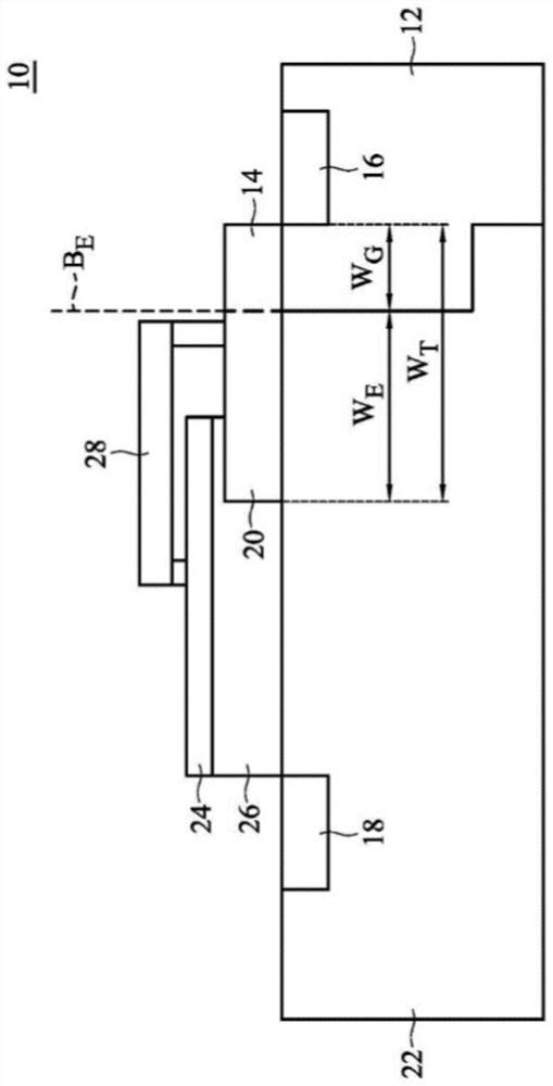
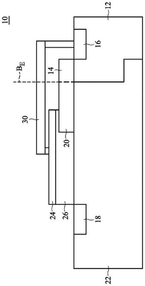
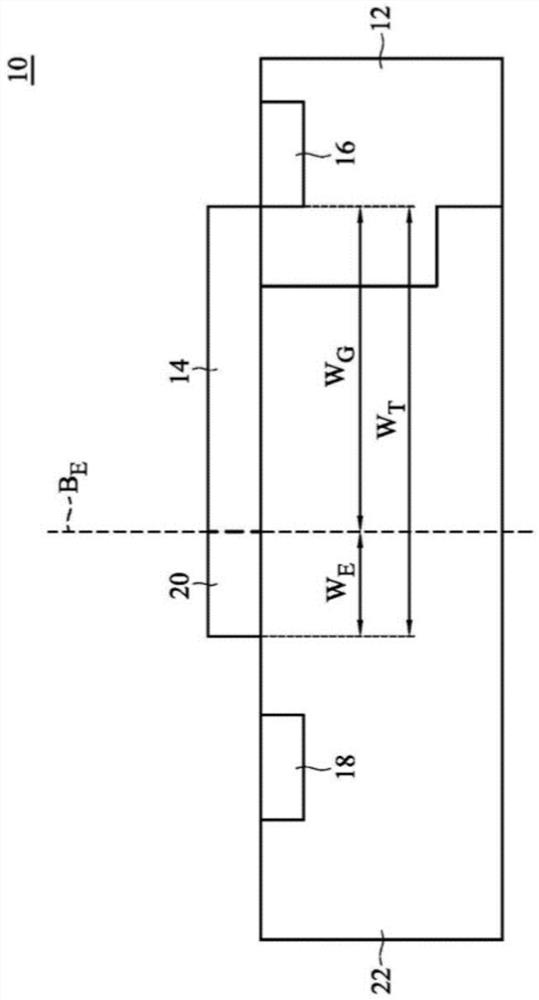
[0036] see figure 1 , according to an embodiment of the present invention, a semiconductor structure (semiconductor structure) 10 is provided. figure 1 is a schematic cross-sectional view of the semiconductor structure 10 .

[0037] like figure 1 As shown, the semiconductor structure 10 includes a substrate 12 , a gate 14 , a source 16 , a drain 18 , a gate extending portion 20 , and a drain drift region 22 . The gate 14 is disposed on the substrate 12 . The source 16 is disposed in the substrate 12 and located on one side of the gate 14 . The drain 18 is dispose...


PUM


Abstract

The invention provides a semiconductor structure which comprises a substrate; a grid electrode which is arranged on the substrate; a source electrode which is arranged in the substrate and located onone side of the grid electrode; a drain electrode which is arranged in the substrate and is positioned on the other side of the grid electrode; a grid extending part which is arranged on the substrateand is positioned between the grid and the drain, wherein the doping type of the grid is opposite to that of the grid extending part. Through the special semiconductor structure design, the power loss of the switching device can be effectively reduced, the switching frequency is greatly improved, and high-efficiency electric power conversion is achieved.

Description

technical field [0001] The present invention relates to a semiconductor structure, and more particularly to a semiconductor structure capable of reducing drain-to-gate capacitance. Background technique [0002] In many semiconductor structures, the field plate structure arranged between the gate and the drain is often used as an important device to disperse the electric field intensity of the drain region (drift region), so as to avoid Excessive concentration of the electric field can cause damage to the device. However, when the field plate structure is electrically connected to its adjacent gate, the field plate structure will also contribute a considerable amount of drain-to-gate capacitance. [0003] Generally speaking, for high-speed switching devices expected to achieve high-efficiency electrical power conversion, it is necessary to try to reduce the power loss during operation as much as possible to maintain high-speed switching between devices. However, when the sw...

Claims


Application Information

Patent Timeline
Patent Type & Authority Applications(China)
IPC IPC(8): H01L29/423H01L29/78
CPCH01L29/78H01L29/42372
Inventor 陈立哲宋建宪林志威谭鸿志
Owner VANGUARD INTERNATIONAL SEMICONDUCTOR CORPORATION
Learn More