Fish seafood processing device

A processing device and seafood technology, which is applied in fish processing, slicing fish, fish cleaning/descaling, etc. It can solve the problems of inability to process large deep-sea fish

Active Publication Date: 2021-01-22
湛江市海洲水产有限公司
View PDF10 Cites 6 Cited by
  • Summary
  • Abstract
  • Description
  • Claims
  • Application Information

AI Technical Summary

Problems solved by technology

The clamping mechanism for fish processing, including the support frame, has good stability, can adjust the fixing jig horizontally and vertically, and can adjust the size of the fixing jig, which is convenient for clamping and fixing fish of different sizes, and is convenient for fish processing, simple operation and convenient use; but this device cannot process large deep-sea fish

Method used


Image

  • Fish seafood processing device
  • Fish seafood processing device
  • Fish seafood processing device

Examples


specific Embodiment approach 1

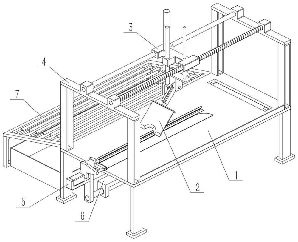
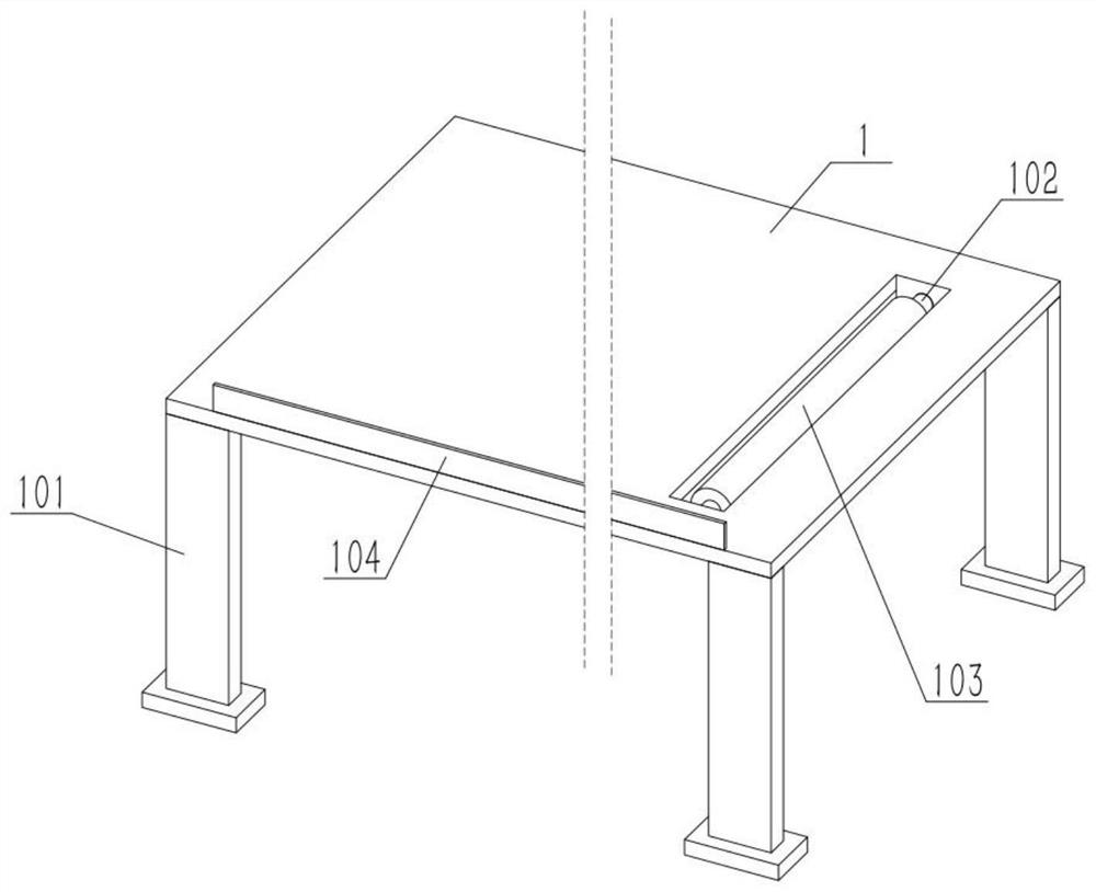
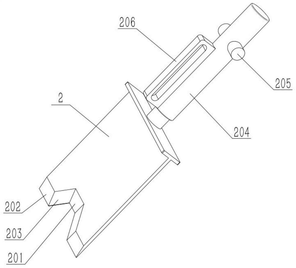
[0030] As shown in the figure, a fish and seafood processing device includes a processing table 1, a supporting foot I101, a plate knife 2, a concave cutting edge 201, a convex cutting edge 202, an inclined cutting edge 203 and an electric push rod I204. The four corners of the lower end of the table top 1 are all connected with a support foot I101, and the board knife 2 is set on the top of the processing table 1 with a low left and a right height, and the board knife 2 is fixed on the movable end of the electric push rod I204, which is used to adjust The position of the panel knife 2 along the inclination direction of the panel knife 2, the electric push rod I204 is installed on the adjustment mechanism, the concave cutting edge 201 is set in the middle of the left end of the panel knife 2, the front and rear ends of the inclined cutting edge 203 and the concave cutting edge 201 The outer ends of the two oblique cutting edges 203 are connected to one convex cutting edge 202 ....

specific Embodiment approach 2

[0032]As shown in the figure, the adjustment mechanism includes shaft II 205, seat with straight notch 206, upper base 3, electric push rod II 301, lower base 303, electric push rod III 304, L-shaped seat 305 and lever 306, the electric push rod The front and rear ends of the upper right side of the rod I204 are fixedly connected to a shaft II205, the upper end of the electric push rod I204 shell is fixedly connected to a straight notch seat 206, and the straight notch seat 206 is located on the left side of the shaft II205, and the upper end of the base 3 is fixed Connect the electric push rod II 301, the movable end of the electric push rod II 301 passes through the upper base 3 from top to bottom, the lower base 303 is fixedly connected to the movable end of the electric push rod II 301, and the two shafts II 205 are connected to the lower base 303 in rotation The lower side of the electric push rod III 304 is fixed on the upper end of the upper base 3, the movable end of th...

specific Embodiment approach 3

[0034] As shown in the figure, the fish and seafood processing device also includes a stabilizing rod 302 , which is slidably connected to the upper base 3 , and the lower end of the stabilizing rod 302 is fixedly connected to the upper end of the lower base 303 .


PUM


Abstract

The invention relates to fish processing, in particular to a fish seafood processing device. The fish seafood processing device comprises a machining table top, supporting legs I, a plate cutter, a concave cutting edge, convex cutting edges, inclined cutting edges and an electric push rod I. The four corners of the lower end of the machining table top are each fixedly connected with one supportingleg I, the plate cutter is obliquely arranged on the upper part of the machining table top with the left portion lower than the right portion, and the plate cutter is fixedly connected to the movableend of the electric push rod I. The electric push rod I is used for adjusting the position of the plate cutter in the inclination direction of the plate cutter and installed on the adjusting mechanism, the concave cutting edge is arranged in the middle of the left end of the plate cutter, the inclined cutting edges are connected with the front end and the rear end of the concave cutting edge, andthe outer ends of the two inclined cutting edges are each connected with one convex cutting edge. The valuable big deep-sea fish can be subjected finish processing, the deep-sea fish does not need tobe clamped during finish process, and a clamping mechanism is not needed.

Description

technical field [0001] The invention relates to fish processing, more specifically to a fish and seafood processing device. Background technique [0002] For example, the publication number is CN109964994A, a clamping mechanism for fish processing. The lower surface of the support frame is provided with a base plate, and the upper surface of the base plate is provided with evenly distributed mounting holes. The internal activities of the mounting holes are interspersed with fixed Bolt, the upper end of the side of the support frame is provided with a chute, the interior of the chute is provided with a lateral movement device, and the circular plate of the lateral movement device is slidably connected with the chute, and the side of the mounting plate of the lateral movement device is provided with a card The slot, the slot is movably clamped with the positioning plate, the upper end of the side of the positioning plate is provided with a push rod, the rear end of the push ro...

Claims


Application Information

Patent Timeline
Patent Type & Authority Applications(China)
IPC IPC(8): A22C25/00A22C25/02A22C25/14A22C25/16
CPCA22C25/00A22C25/02A22C25/142A22C25/145A22C25/16A22C25/163A22C25/14Y02A40/90
Inventor 王亦婷
Owner 湛江市海洲水产有限公司
Why Eureka
Try Eureka