Odor removing device of textile equipment

A technology for textile equipment and deodorization, which is applied in the direction of removing smoke and dust, using liquid separating agent, cleaning methods and utensils, etc. It can solve problems such as equipment failure, damage, pungent nose, etc., and achieve high versatility and prevent clogging effects

Pending Publication Date: 2021-01-22
绍兴金诚达纺织股份有限公司
View PDF7 Cites 1 Cited by
  • Summary
  • Abstract
  • Description
  • Claims
  • Application Information

AI Technical Summary

Problems solved by technology

[0002] When the equipment in the textile factory is working, because some processes need to apply dyes, a lot of peculiar smell will be generated in the equipment. These peculiar smells are not only pungent, but also pose a threat to the health of the staff if absorbed for a long time. The deodorizing devices of textile equipment are often large in structure and need to be designed according to the mechanical structure of the production equipment. The transformation cost is high, and the proportion of cotton dust in the air in the textile factory is very high. These dust flocs will be seriously blocked after being absorbed by the purification device. The gas pipeline of the purification device, causing equipment failure and damage

Method used


Image

  • Odor removing device of textile equipment
  • Odor removing device of textile equipment
  • Odor removing device of textile equipment

Examples


Embodiment 1

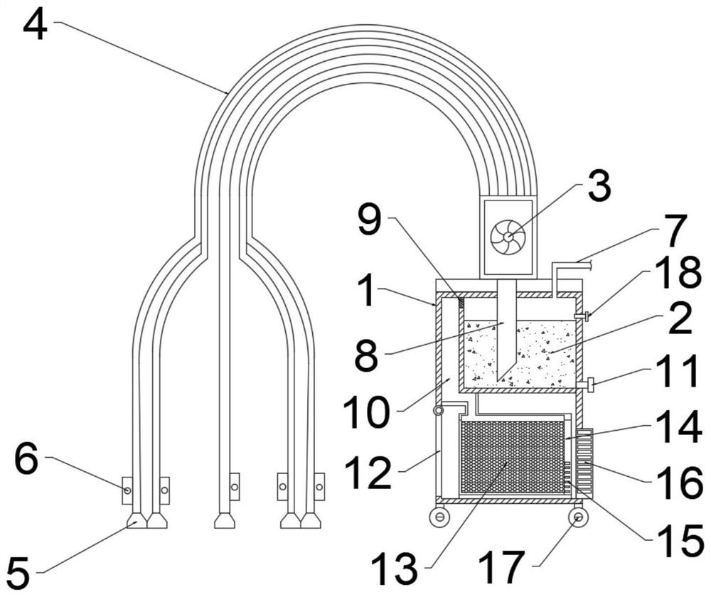
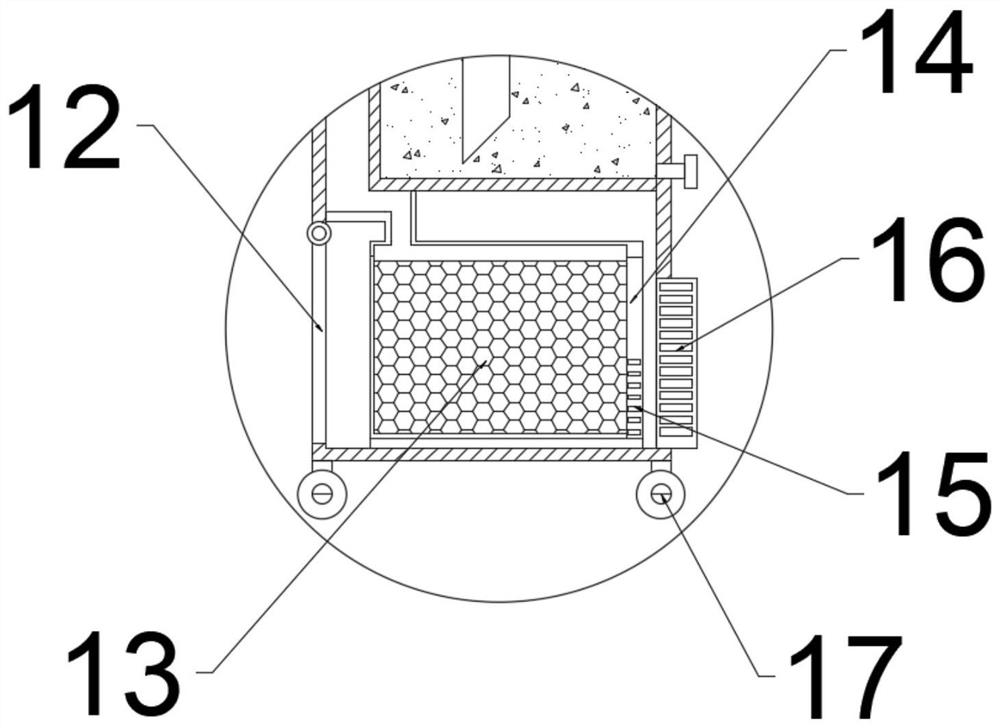
[0023] see Figure 1 ~ Figure 2 , a kind of deodorization device for textile equipment, including deodorization box 1, dedusting pool 2, elbow 4 and drawer box 14, wherein the dedusting pool 2 for absorbing cotton dust is installed on the top of deodorization box 1 for absorbing gas The elbow 4 is installed on the outside of the deodorization box 1, and the drawer 14 for holding the activated carbon 13 is installed on the bottom of the deodorization box 1.

[0024] The top of the deodorization box 1 is provided with an air pump 3, the upper end of the air pump 3 is connected with the elbow 4, the lower end of the air pump 3 is fixedly connected with the deodorization box 1, and an air inlet 8 is arranged below the air pump 3, and the air inlet 8 passes through the deodorization box 1. The upper surface is installed inside the dust-suppression pool 2. The end of the elbow 4 is connected with a gas-collecting hood 5. A fixing plate 6 for fixing the gas-collecting hood 5 is insta...

Embodiment 2

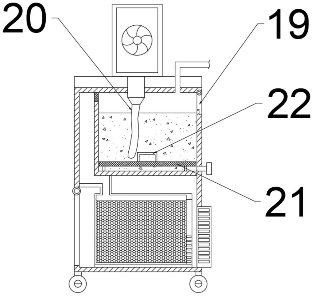
[0028] see image 3 , a textile equipment odor removal device, the main structure of which is the same as that of Example 1, the intake pipe 8 in Example 1 is replaced by a hose 20, the lower end of the hose 20 is placed inside the dust suppression pool 2, and the bottom of the dust suppression pool 2 is set There is a net plate 21, and the net plate 21 is slidingly matched with the inner wall of the dust-suppression pool 2. A handle 22 is arranged above the net plate 21, and the handle 22 is fixedly connected with the net plate 21. A pull plate 19 is arranged on the upper right corner of the dust-suppression pool 2, and the pull plate 19 passes through a hinge. Connect with deodorizing box 1 activity.

[0029] The working principle of the present invention is: when excessive cotton dust has accumulated in the aqueous solution inside the dust-removing pool 2 and affects the purification of odor gas, the staff first opens the blowdown valve 11 to allow the liquid phase of the i...


PUM


Abstract

The invention discloses an odor removing device of textile equipment, and belongs to the technical field of textile. The odor removing device comprises an odor removing box, a dust falling pool, a bent pipe and a drawing box. The dust falling pool used for adsorbing cotton dust is mounted at the upper part of the odor removing box, the bent pipe used for sucking gas is mounted outside the odor removing box, and the drawing box used for containing activated carbon is mounted at the bottom of the odor removing box. A gas pump is arranged at the top of the odor removing box, the upper end of thegas pump is connected with the bent pipe, a gas channel is arranged between the left side of the dust falling pool and the odor removing box, the drawing box is arranged below the gas channel, a movable plate is arranged on the left side of the drawing box and movably connected with the odor removing box through a hinge, meshes are formed in the lower right corner of the drawing box, and an exhaust pipe is arranged on the right side of the drawing box and fixedly mounted at the lower right corner of the odor removing box. The device can be suitable for various types of textile equipment through the bendable bent pipe, high universality is achieved, meanwhile, large-particle dust impurities such as cotton dust contained in peculiar smell gas can be effectively removed through the dust falling pool, and a gas purification pipeline is prevented from being blocked.

Description

technical field [0001] The invention relates to the technical field of textiles, in particular to a deodorizing device for textile equipment. Background technique [0002] When the equipment in the textile factory is working, because some processes need to apply dyes, a lot of peculiar smell will be generated in the equipment. These peculiar smells are not only pungent, but also pose a threat to the health of the staff if absorbed for a long time. The deodorizing devices of textile equipment are often large in structure and need to be designed according to the mechanical structure of the production equipment. The transformation cost is high, and the proportion of cotton dust in the air in the textile factory is very high. These dust flocs will be seriously blocked after being absorbed by the purification device. The gas pipeline of the purification device will cause equipment failure and damage. [0003] Therefore, there is a need to provide a deodorizing device for textile...

Claims


Application Information

Patent Timeline
Patent Type & Authority Applications(China)
IPC IPC(8): B08B15/04B01D47/02B01D53/02
CPCB08B15/04B01D47/02B01D53/02B01D2253/102B01D2257/90
Inventor 高成轶
Owner 绍兴金诚达纺织股份有限公司
Why Eureka
Try Eureka