
Three-roller differential variable-curvature numerical control rolling machine

A plate rolling machine and quick-change technology, applied in the directions of forming tools, safety equipment, cleaning methods and utensils, etc., can solve the problems of reducing the applicability of the plate rolling machine, reducing the work efficiency, reducing the gear speed, etc., to achieve safe use, improve Efficiency and high stability

Inactive Publication Date: 2021-01-22
王悦
View PDF6 Cites 0 Cited by
  • Summary
  • Abstract
  • Description
  • Claims
  • Application Information

AI Technical Summary

Problems solved by technology

[0004] The object of the present invention is to provide a three-roller differential speed variable curvature CNC plate rolling machine to solve the problem that it is very inconvenient to replace the rolls after the current plate rolling machine proposed in the background technology is used, thereby greatly reducing the This improves the applicability of the plate rolling machine. At the same time, dust is easily stuck between the gears of the rotating shaft, thereby reducing the speed of the gears, thereby reducing the problem of work efficiency.

Method used


Image

  • Three-roller differential variable-curvature numerical control rolling machine
  • Three-roller differential variable-curvature numerical control rolling machine
  • Three-roller differential variable-curvature numerical control rolling machine

Examples


Embodiment Construction

[0021] The following will clearly and completely describe the technical solutions in the embodiments of the present invention with reference to the accompanying drawings in the embodiments of the present invention. Obviously, the described embodiments are only some, not all, embodiments of the present invention. Based on the embodiments of the present invention, all other embodiments obtained by persons of ordinary skill in the art without making creative efforts belong to the protection scope of the present invention.

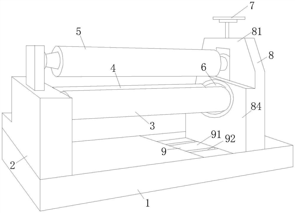
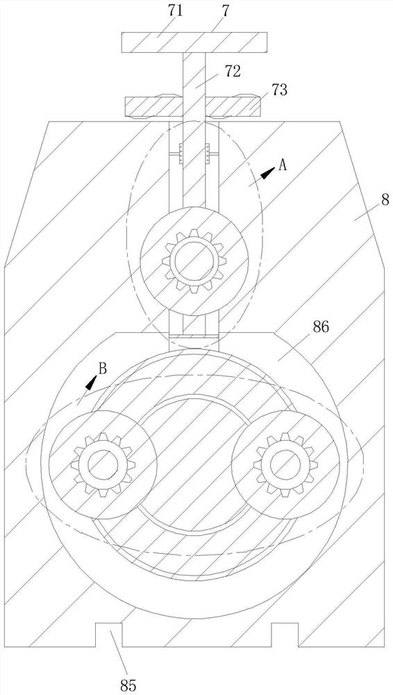
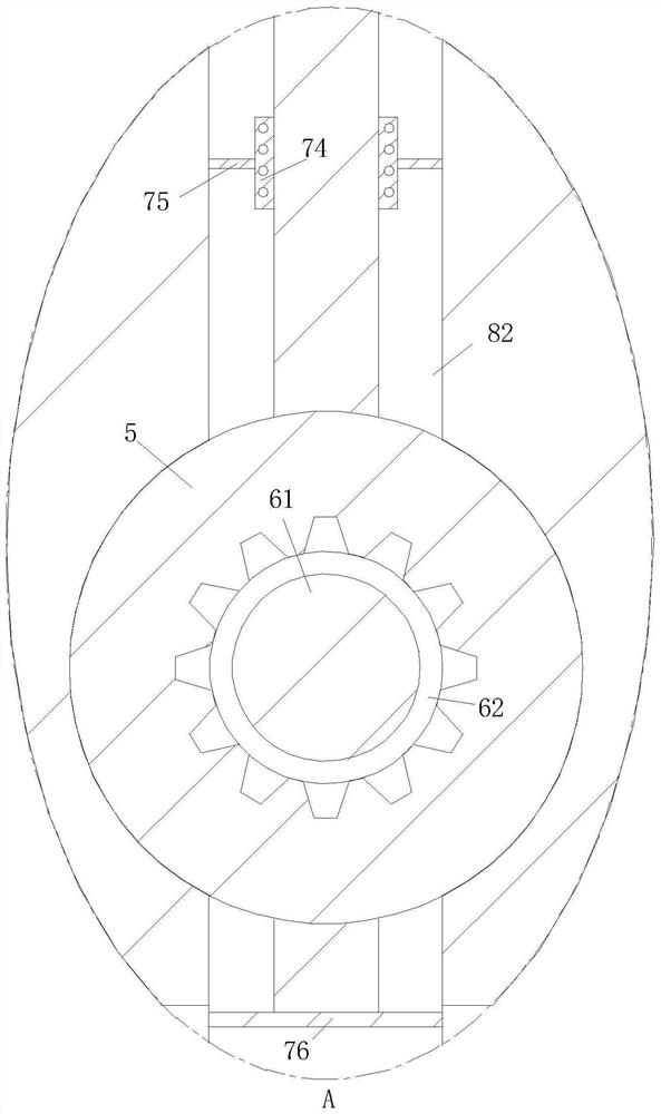
[0022] see Figure 1-5 As shown, the present invention provides a three-roller differential speed variable curvature CNC plate rolling machine, including a base 1, a first stand 2, a side roll 3, a lower roll 4, an upper roll 5, a transmission mechanism 6, and an air suction mechanism 7 , the second stand 8 and the sliding seat mechanism 9, the upper end of the front side of the base 1 is fixedly installed with the first stand 2, the upper end of the rear side...


PUM


Abstract

The invention relates to the technical field of rolling machines, in particular to a three-roller differential variable-curvature numerical control rolling machine. The three-roller differential variable-curvature numerical control rolling machine comprises a base, a first vertical base, a side roller, a lower roller, an upper roller, a transmission mechanism, an air suction mechanism, a second vertical base and a sliding base mechanism, wherein the first vertical base is fixedly installed at the upper end of the front side of the base, the sliding base mechanism is arranged at the upper end of the rear side of the base, the second vertical base is slidably installed at the upper end of the sliding base mechanism, the air suction mechanism is fixedly installed at the upper end of the second vertical base, and the transmission mechanism is fixedly installed on the inner side of the second vertical base. According to the three-roller differential variable-curvature numerical control rolling machine, a circular shaft is adopted to slide in a sliding groove of a circular ring for use, the interior is firmer and tighter through overlapping rotation, on the one hand, the stability of usein the groove is improved, and then the use is safer; and on the other hand, an air suction fan is arranged on the transmission mechanism, the air suction fan is dragged by a rotating rod while the upper roller is driven to move, air convection is formed, then the interior of the transmission mechanism is effectively cleaned, dust accumulation is avoided, and the working efficiency is greatly improved.

Description

technical field [0001] The invention relates to the technical field of plate rolling machines, in particular to a three-roller differential speed variable curvature numerical control plate rolling machine. Background technique [0002] The plate rolling machine is a kind of equipment that uses work rolls to bend and form the sheet metal. It can form parts of different shapes such as cylindrical parts and conical parts. It is a very important processing equipment. The working principle of the plate rolling machine is to move the work roll through the action of hydraulic pressure, mechanical force and other external forces, so that the plate is bent or rolled into shape. According to the rotation movement and position changes of the work rolls of different shapes, oval parts, arc parts, cylindrical parts and other parts can be processed. [0003] After the current plate rolling machine is used, it is very inconvenient to replace the rollers, which greatly reduces the applicab...

Claims


Application Information

Patent Timeline
IPC IPC(8): B21D5/08B21D37/04B21D55/00B08B5/04
CPCB21D5/08B21D37/04B21D55/00B08B5/04
Inventor 王悦林胜男
Owner 王悦
Learn More