Eureka AIR delivers breakthrough ideas for toughest innovation challenges, trusted by R&D personnel around the world.

Reserved heat pipe mounting device

A mounting device and heat pipe technology, applied in the field of reserved heat pipe installation devices, can solve the problems of low heat dissipation efficiency, low heat pipe bending quality, low production efficiency of LED heat dissipation modules, etc., and achieve the goal of increasing the contact area and improving heat dissipation efficiency Effect

Inactive Publication Date: 2021-01-22
长丰吾道智能光电科技有限公司
View PDF0 Cites 0 Cited by
  • Summary
  • Abstract
  • Description
  • Claims
  • Application Information

AI Technical Summary

Problems solved by technology

In the prior art, when the above-mentioned heat dissipation module is assembled and processed, the heat dissipation fins are first welded and fixed by welding equipment, and the interface of the heat pipe is reserved on the heat dissipation fin. After the LED module is connected to the heat pipe, the heat pipe By bending and connecting with the reserved heat pipe interface on the heat dissipation module, the LED heat dissipation module is formed. When the above-mentioned LED heat dissipation module is actually produced and assembled, because the heat pipe needs to be bent, it presents a divergent shape and the reserved heat pipe on the heat dissipation module. Interface connection, so in the prior art, manual bending and installation are often used, resulting in low production efficiency of the LED heat dissipation module, poor bending quality of the heat pipe, and poor fit with the heat dissipation module, resulting in low heat dissipation efficiency

Method used


Image

  • Reserved heat pipe mounting device
  • Reserved heat pipe mounting device
  • Reserved heat pipe mounting device

Examples


Embodiment Construction

[0032] In order to make the objects and advantages of the present invention clearer, the present invention will be described in detail below in conjunction with the examples. It should be understood that the following words are only used to describe one or several specific implementation modes of the present invention, and do not strictly limit the protection scope of the specific claims of the present invention. As used herein, the terms "parallel" and "perpendicular" are not limited to their strict geometric definitions, but include reasonable and inconsistent tolerances for machining or human error;

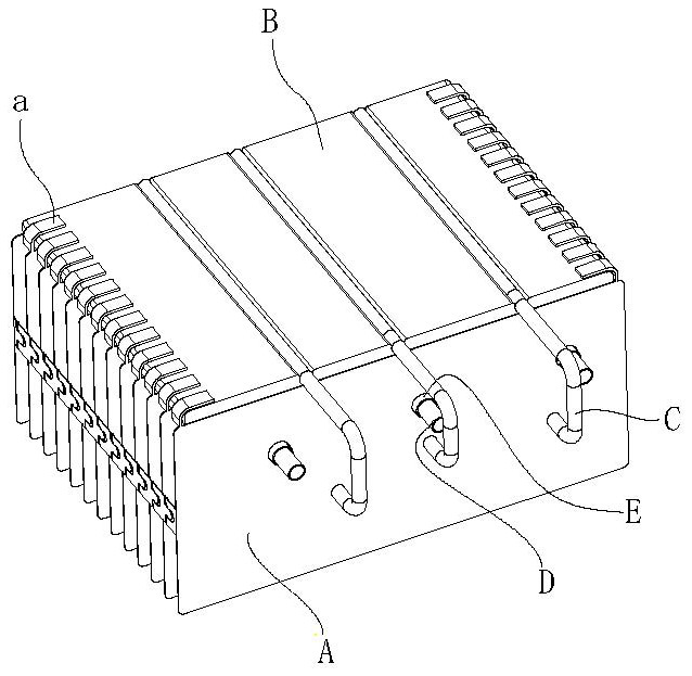
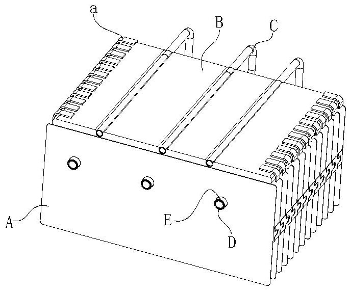
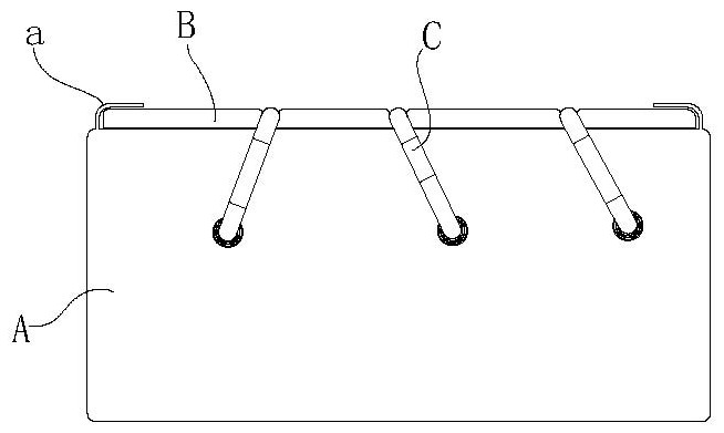
[0033] The following is a detailed description of the invented reserved heat pipe installation device in conjunction with the entire radiator automatic production system:

[0034] combine Figure 1 to Figure 4 As shown, the structure of the heat sink is composed of a plurality of heat dissipation fins A arranged in parallel and at intervals. Positioning blocks are arranged on...


PUM


Abstract

The invention relates to a reserved heat pipe mounting device. A welding unit carries out welding operation on cooling fins and the outer wall of a nickel metal pipe; a material guide rail is obliquely arranged; a positioning arc plate is arranged at the lower end of the material guide rail; a heat pipe rail is arranged on the other side of the positioning plate, and a guiding and conveying arc plate is arranged at the lower end of the heat pipe rail; the reserved heat pipe mounting device further comprises a first mounting pipe; a driving unit is mounted to drive the first mounting pipe to move horizontally and is in linkage with a reserved heat pipe to be inserted into holes of the cooling fins; the reserved heat pipe mounting device further comprises a second mounting pipe, and a powerunit drives the second mounting pipe and is in linkage with a nickel alloy pipe to be arranged outside the heat pipe in a sleeved mode; after the punching operation of the cooling fins is finished, the reserved heat pipe is inserted into the holes of the radiating fins, and then the power unit drives the second mounting pipe and the nickel alloy pipe is arranged outside the heat pipe in a sleevedmode, so that the punching flanging of the cooling fins abuts against the outside of the nickel alloy pipe, the contact area with the cooling fins is increased, and the radiating efficiency is improved.

Description

technical field [0001] The invention relates to the technical field of LED cooling equipment, in particular to a reserved heat pipe installation device. Background technique [0002] When large-scale LEDs are actually used, the LED module will generate a lot of heat. It is necessary to effectively dissipate heat from the LED module to ensure the normal use of the LED. The LED module is installed on the heat dissipation module, and the general heat dissipation module has heat dissipation fins. The heat dissipation fins are connected to each other as a whole, and heat pipes are set on the heat dissipation fins. The heat generated by the LED module is transported to the heat dissipation fins through the heat pipes, thereby effectively improving the heat dissipation efficiency of the LED module. . In the prior art, when the above-mentioned heat dissipation module is assembled and processed, the heat dissipation fins are first welded and fixed by welding equipment, and the inter...

Claims


Application Information

Patent Timeline
Patent Type & Authority Applications(China)
IPC IPC(8): B23P15/26
CPCB23P15/26
Inventor 曹茂兵
Owner 长丰吾道智能光电科技有限公司
Why Eureka
Eureka Blog
Learn More