Positioning and clamping tool for shell part

A positioning clamping and tooling technology, which is applied in the field of positioning clamping tooling, workpiece processing, positioning and clamping tooling of shell parts, can solve the problems such as difficulty in guaranteeing dimensional accuracy and shape and position tolerance, so as to improve processing efficiency and reduce deformation effect, easy operation

Inactive Publication Date: 2021-01-22
HARBIN JIANCHENG GRP
View PDF8 Cites 0 Cited by
  • Summary
  • Abstract
  • Description
  • Claims
  • Application Information

AI Technical Summary

Problems solved by technology

[0003] The purpose of the present invention is to solve the problem that the dimensional accuracy and shape and position tolerance are difficult to guarantee in the processing of existing shell parts, and to provide a positioning and clamping tool for shell parts

Method used


Image

  • Positioning and clamping tool for shell part
  • Positioning and clamping tool for shell part
  • Positioning and clamping tool for shell part

Examples


specific Embodiment approach 1

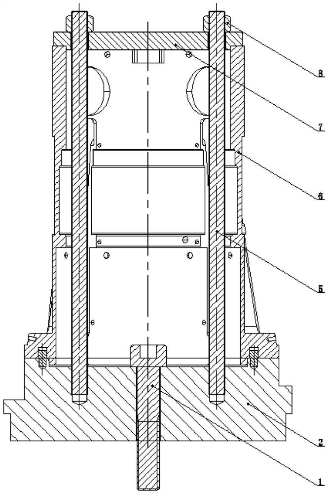
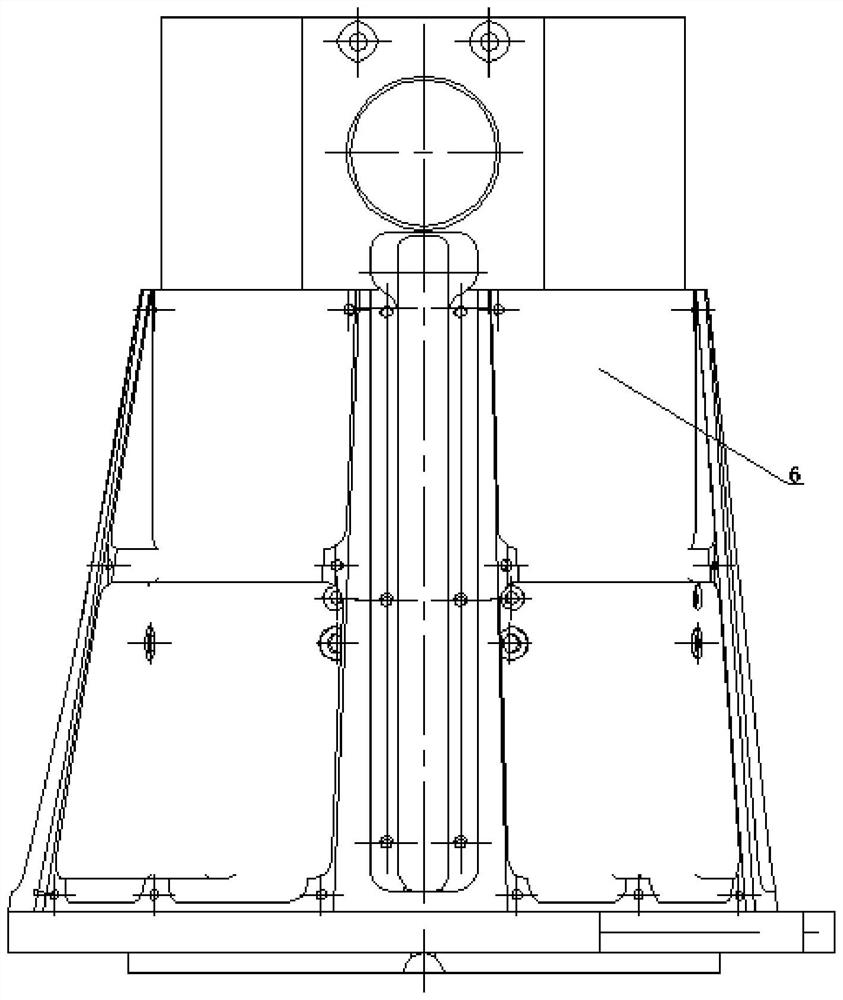
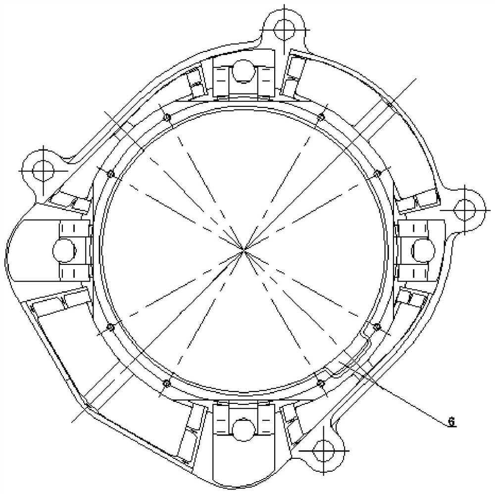
[0021] Specific implementation mode one: combine Figure 1-Figure 11 Describe this embodiment, the positioning and clamping tooling of shell parts described in this embodiment, which includes connecting screws 1, tooling base 2, positioning pin assembly, tooling gland 7, multiple studs 5 and multiple Nut 8; the tooling gland 7 is a plate body whose upper end surface and lower end surface are parallel, the lower end surface of the tooling gland 7 is processed with protrusions, and the tooling gland 7 is uniformly processed with a plurality of through holes, and the tooling base 2 is the upper end surface The plate body parallel to the lower end surface, the upper end surface of the tooling base 2 is processed with grooves, the groove bottom of the upper end surface groove of the tooling base 2 is processed with through holes and multiple threaded holes, and the side wall of the upper end surface groove of the tooling base 2 Blind holes are processed, and the positioning pin ass...

specific Embodiment approach 2

[0022] Specific implementation mode two: combination Figure 1-Figure 7 Describe this embodiment, a positioning and clamping tool for shell parts. The cooling joint 2 includes a connecting plate and a coolant connection end. It is arranged in cooperation with the low-end convex shape of the part 6 to ensure the accuracy of the clamping and positioning of the part 6 by the positioning and clamping tooling. Others are the same as the first embodiment.

specific Embodiment approach 3

[0023] Specific implementation mode three: combination figure 1 and Figure 10 Describe this embodiment, a positioning and clamping tool for shell parts, the positioning pin assembly is two first positioning pins 3, the diameter of the first positioning pin 3 is 5mm, the positioning pin mounting hole at the bottom of the part 6 and the tooling base 2 The top blind hole is positioned by the first positioning pin 3. During rough machining, it is only necessary to insert the first positioning pin 3 into the positioning pin hole where the first positioning pin 3 is installed at the bottom of the part 6 and insert the first positioning pin 3 at the top of the tooling base 2. The blind holes are the same as those in Embodiment 1.


PUM


Abstract

The invention relates to a positioning and clamping tool, specifically relates to a positioning and clamping tool for a shell part, and aims to solve the problem that the dimensional accuracy and thegeometric tolerance are difficult to guarantee in the conventional shell part machining process. The positioning and clamping tool comprises connecting screws, a tool base, a positioning pin assembly,a tool gland, double-end studs and a plurality of nuts, a protrusion is machined on the lower end surface of the tool gland, a plurality of through holes are uniformly distributed and machined in thetool gland, the tool base is a plate body with the upper end surface and the lower end surface parallel to each other, a groove is machined in the upper end surface of the tool base, the part is arranged on the tool base, the bottom end of the part is arranged in the groove in the upper end surface of the tool base in a protruding mode, the part and the tool base are located through the positioning pin assembly, each threaded hole of the tool base is vertically connected with one double-end stud in a threaded mode, the connecting screws are inserted into the through holes of the tool base, and the tool base is arranged on the threaded holes of a flange plate of a three-jaw chuck through the connecting screws and clamped through the three-jaw chuck. The positioning and clamping tool is applied to the field of machining.

Description

technical field [0001] The invention relates to a positioning and clamping tool, in particular to a positioning and clamping tool for shell parts, which is used for workpiece processing and belongs to the field of mechanical processing. Background technique [0002] The shell parts of the executive cabin belong to the thin-walled shell parts. The shape and structure of these parts are usually very complicated, and most of them are made of aluminum alloy. The processing deformation is large, but the dimensional accuracy and shape tolerance requirements are very strict. If you want to mill the shell parts, you need to clamp and align the parts; if you want to ensure the dimensional accuracy, shape tolerance and processing efficiency of the parts, you need to ensure that the clamping is convenient, stable and reliable. Since most of the shell parts are thin-walled aluminum alloy parts, the processing deformation is large, so they cannot be processed and formed at one time. Dim...

Claims


Application Information

Patent Timeline
Patent Type & Authority Applications(China)
IPC IPC(8): B23Q3/12
CPCB23Q3/12
Inventor 马明礼王智莉张洪海高伟王青
Owner HARBIN JIANCHENG GRP
Why Eureka
Try Eureka