Biological experiment slicing device

A slicing device and bio-experimental technology, which is applied in metal processing and other directions, can solve the problems of inability to accurately adjust the slice thickness, uneven slice thickness, and incomplete tissue cut, so as to improve slice quality and practicability, improve slice efficiency, size, etc. same effect

Inactive Publication Date: 2021-01-22
李世军
View PDF0 Cites 5 Cited by
  • Summary
  • Abstract
  • Description
  • Claims
  • Application Information

AI Technical Summary

Problems solved by technology

[0003] The thickness of the slices cut by the existing slicing device is uneven, and the tissue is cut incompletely, which is not conducive to the later experiment, and at the same time, the slice thickness cannot be adjusted precisely

Method used


Image

  • Biological experiment slicing device
  • Biological experiment slicing device
  • Biological experiment slicing device

Examples


Embodiment 1

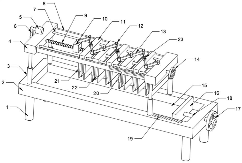
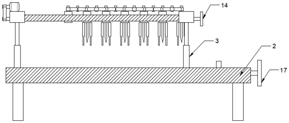
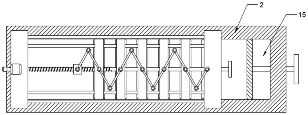
[0025] see Figure 1-4 , a biological experiment slicing device, including a column 1 and a placement plate 2, the placement plate 2 is provided with a slicing assembly, the specific type of the slicing assembly is not limited, in this embodiment, preferably, the slicing assembly includes a cylinder 3 , mounting plate 4, guide rod 7, screw mandrel 9, slide block 10, adjustment block 11, limit pin 12, connecting rod 13, cutter 22 and rotating shaft 23, the two ends of two mounting plates 4 are installed by cylinder 3 On the placement plate 2, the two ends of the two guide rods 7 are fixedly installed on the two mounting plates 4, and a plurality of adjustment blocks 7 are movably sleeved on the upper and middle parts of the guide rods 7. There are through holes, and the screw rods 9 run through the through holes. , the two ends are rotatably installed in the two mounting plates 4 and one end extends to the outside of the mounting plate 4 and is connected with a drive member, th...

Embodiment 2

[0034]In order to improve the quality of slicing, this embodiment is further improved on the basis of Embodiment 1. The improvement is that: the two sides of the cutter 22 are provided with pressing plates 21, and the specific type of the pressing plate 21 is not limited. In this embodiment, Preferably, the pressing plate 21 includes a sleeve plate 2101, a pressing plate 2102 and a return spring 2103, the sleeve plate 2101 is fixedly installed on the adjustment block 11, and the upper end of the pressing plate 2102 is movably sleeved in the sleeve plate 2101 and between the sleeve plate 2101 A return spring 2103 is provided, and when the cylinder 3 works, the pressing plate 2102 first contacts with the article to be cut and fixes it, and then during the descent of the cutter 22, the return spring 2103 is compressed to make the article firmly fixed before slicing. Improved slice quality and usability.

[0035] To sum up, by setting the slicing component, when slicing the item, ...


PUM


Abstract

The invention discloses a biological experiment slicing device. The device comprises a column and a placing plate, a slicing assembly is arranged on the placing plate, the slicing assembly comprises cylinders, mounting plates, guide rods, a screw rod, a sliding block, adjusting blocks, limiting pins, connecting rods, cutters and rotating shafts, two ends of the two mounting plates are mounted on the placing plate through the cylinders, two ends of the two guide rods are fixedly arranged on the two mounting plates, the multiple adjusting blocks are movably arranged on the guide rods in a sleeved mode, through holes are formed in the upper middle portions of the adjusting blocks, the screw rod penetrates through the through holes, two ends of the screw rod are rotatably arranged in the two mounting plates, one end extends out of the mounting plate to be connected with a driving piece, the slide block is arranged on the screw rod, the rotating shafts are rotatably arranged on the slidingblock, the adjusting blocks and the ends, away from the sliding block, of the mounting plates, the multiple connecting rods are rotatably arranged on the rotating shafts, the outer ends of the adjacent connecting rods are hinged through the limiting pins, and the cutters are fixedly arranged on the lower surfaces of the adjusting blocks. The practicability and the slicing efficiency are improved by the arrangement of the slicing assembly.

Description

technical field [0001] The invention relates to the field of biotechnology, in particular to a biological experiment slicing device. Background technique [0002] In the process of biological experiments, sometimes in order to observe the basic structure and shape of plant tissues and cells more clearly, plant samples are often cut. [0003] The thickness of slices cut out by the existing slicing device is not uniform, and the tissue is cut incompletely, which is not conducive to the later experiment, and at the same time, the slice thickness cannot be adjusted precisely. Contents of the invention [0004] The object of the present invention is to provide a bio-experiment slicing device to solve the problems raised in the above-mentioned background technology. [0005] To achieve the above object, the present invention provides the following technical solutions: [0006] A biological experiment slicing device, comprising a column and a placement plate, the slicing assemb...

Claims


Application Information

Patent Timeline
Patent Type & Authority Applications(China)
IPC IPC(8): B26D1/09B26D7/20B26D5/12B26D7/26B26D7/02
CPCB26D1/09B26D5/12B26D7/02B26D7/20B26D7/2628
Inventor 李世军金立波赵海洋李斌李小芬
Owner 李世军
Why Eureka
Try Eureka