Frame longitudinal beam transfer lifting appliance and application method thereof

A longitudinal beam and frame technology, which is applied in the field of frame longitudinal beam transfer spreader, can solve the problems of low degree of automation, low safety, complicated operation, etc., and achieves the effects of high degree of automation, high safety, and improved production efficiency.

Active Publication Date: 2021-01-22
DONGFENG AUTOMOBILE COMPANY
View PDF5 Cites 2 Cited by
  • Summary
  • Abstract
  • Description
  • Claims
  • Application Information

AI Technical Summary

Problems solved by technology

[0006] The purpose of the present invention is to overcome the defects and problems of low security, low degree of automation and cumbersome operation in the prior art, and provide a high security, automatic High-degree, easy-to-operate vehicle frame longitudinal beam transfer spreader and using method thereof

Method used


Image

  • Frame longitudinal beam transfer lifting appliance and application method thereof
  • Frame longitudinal beam transfer lifting appliance and application method thereof
  • Frame longitudinal beam transfer lifting appliance and application method thereof

Examples


Embodiment 1

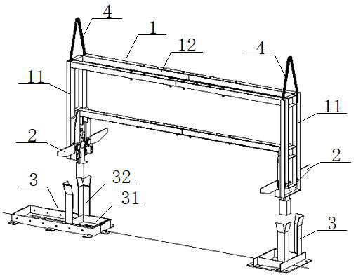
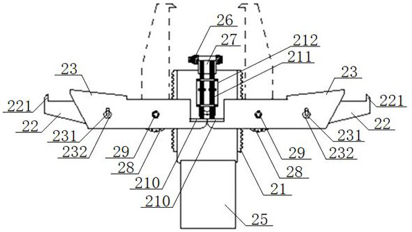
[0056] see Figure 1 to Figure 4 , a frame longitudinal beam transfer spreader, including a frame 1, a support arm device 2 and a guide base 3, the top of the frame 1 is symmetrically connected with two lifting rings 4, and the bottom of the frame 1 is symmetrically connected with two support arm devices 2. A guide base 3 is provided below the support arm device 2, and the support arm device 2 includes a tooth plate 21, two support arms 22 symmetrically arranged on both sides of the tooth plate 21, and two support arm rotation control plates 23 , the tooth plate 21 is slidingly connected with the frame 1, the top of the tooth plate 21 is connected with a fixed hook 24, the bottom of the tooth plate 21 is connected with a drop block 25, and the position above the tooth plate 21 on the frame 1 is equipped with a hook support Seat 26, the locking hook 27 that matches with fixed hook 24 is rotatably connected on the hook support 26, and the end of described support arm 22 is conne...

Embodiment 2

[0063] Basic content is the same as embodiment 1, the difference is:

[0064] see Figure 2 to Figure 6 The locking hook 27 includes a lifting plate 271 and a hook body 272 matched with the fixed hook 24, the lifting plate 271 is connected to the hook body 272 through a pair of protrusions 273, and the protrusion 273 is connected to the hook body 272 through a bolt 274. The hook support 26 is rotatably connected, and a torsion spring 275 is set on the bolt 274 between a pair of protrusions 273. One end of the torsion spring 275 rides on the hook support 26, and the other end of the torsion spring 275 rides on the hook support 26. On the upper surface of the lifting plate 271 , the top of the lifting rod 211 abuts against the lower surface of the lifting plate 271 .

Embodiment 3

[0066] Basic content is the same as embodiment 1, the difference is:

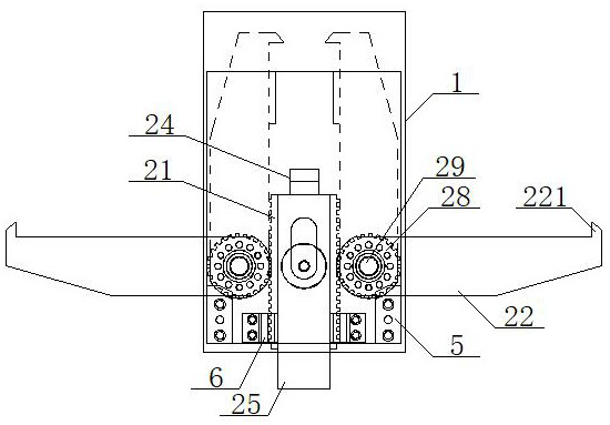
[0067] see Figure 2 to Figure 4 , the position on the shaft 29 located inside the bracket arm rotation control plate 23 is connected with a limit plate, and the bracket arm rotation control plate 23 is provided with a through hole 231, and a limit plate connected with the limit plate is inserted in the through hole 231. position pin 232; the upper surface of the bracket arm 22 away from the gear 28 is provided with a protrusion 221; the position below the bracket arm 22 on the frame 1 is connected with the bracket arm limit block 5; The positions on both sides of the plate 21 are connected with tooth plate limiting blocks 6 , and the tooth plate limiting blocks 6 are provided with limiting slots matching the tooth plate 21 .


PUM


Abstract

The invention relates to a frame longitudinal beam transfer lifting appliance which comprises a frame, a supporting arm device and a guide base. The supporting arm device comprises a toothed plate, two supporting arms and two supporting arm rotating control plates; the two supporting arms and the two supporting arm rotating control plates are symmetrically arranged on the two sides of the toothedplate; the toothed plate is slidably connected with the frame; the top of the toothed plate is connected with a fixing hook; the bottom of the toothed plate is connected with a falling block; a hook support is installed at the position, located above the toothed plate, of the frame; a locking hook matched with the fixing hook is rotatably connected onto the hook support; gears are connected to theends of the supporting arms and are installed on the frame through shafts; the gears are meshed with the toothed plate; the supporting arm rotating control plates are rotatably connected with the shafts; a supporting plate is connected to the ends of the supporting arm rotating control plates; the supporting plate is connected with the bottom of a lifting rod; the top of the lifting rod abuts against the locking hook; the lifting rod is installed on a lifting base; the lifting rod is sleeved with a reset spring; and the lifting base is installed on the frame. The design is high in safety, high in automation degree and simple and convenient to operate.

Description

technical field [0001] The invention belongs to the technical field of automobile production slings, and in particular relates to a vehicle frame longitudinal beam transfer sling and a using method thereof, which are mainly suitable for improving safety and automation and reducing operation difficulty. Background technique [0002] In order to meet the market demand, there are more and more light truck models, and the types of frame longitudinal beams also increase accordingly. Apart from the change of the position of the process hole, the biggest difference is that the length of the longitudinal beams varies greatly; It can be divided into three parts. The first part is to realize the movement of the left and right longitudinal beams through the ring chain hook, and the tail part is to use the ground drag chain to realize the assembly, riveting and off-line of the frame. For the realization of the special spreader, the following problems need to be solved in the process of ...

Claims


Application Information

Patent Timeline
Patent Type & Authority Applications(China)
IPC IPC(8): B66C1/10B66C1/22
CPCB66C1/10B66C1/22Y02T10/40
Inventor 魏明伟郭俊斌韩涛陈红梅王宜乐毅
Owner DONGFENG AUTOMOBILE COMPANY
Why Eureka
Try Eureka