Automatic loading and unloading type gear induction quenching device
An induction hardening equipment, automatic loading and unloading technology, applied in the direction of quenching device, heat treatment equipment, furnace type, etc., can solve the problems of easily scalded hands and low work efficiency, and achieve the effect of avoiding gear re-sticking and improving work efficiency
- Summary
- Abstract
- Description
- Claims
- Application Information
AI Technical Summary
Problems solved by technology
Method used
Image
Examples
Embodiment 1
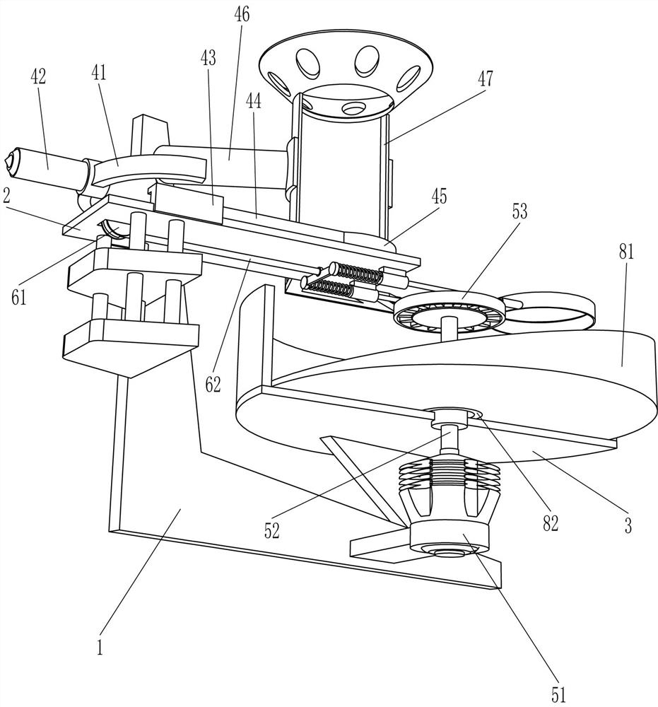
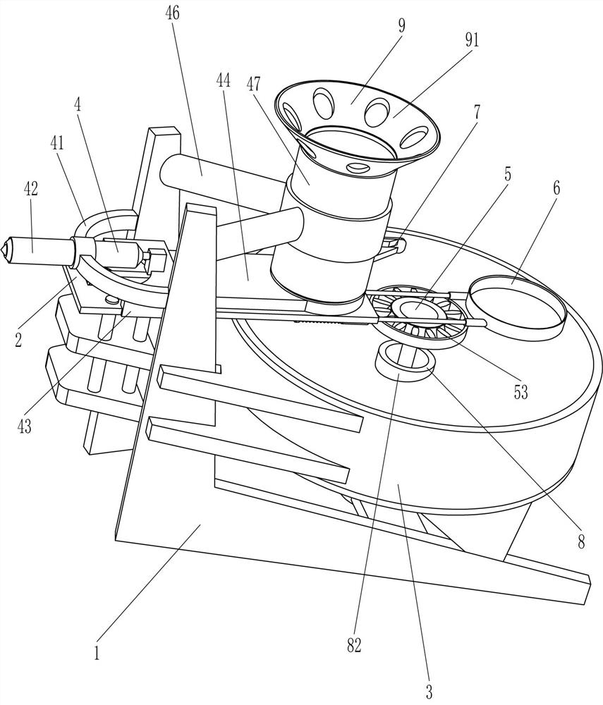
[0057] An automatic loading and unloading gear induction hardening equipment, such as figure 1 As shown, it includes a mounting frame 1, a horizontal plate 2, a cooling pool 3, a discharge mechanism 4, a rotating mechanism 5, and a discharge mechanism 6. The horizontal plate 2 is connected to the left side of the mounting frame 1, and the cooling plate is connected to the right side of the mounting frame 1. Pool 3, the horizontal plate 2 is located on the upper side of the cooling pool 3, a discharge mechanism 4 is connected between the horizontal plate 2 and the mounting frame 1, a rotating mechanism 5 is connected to the cooling pool 3, and the horizontal plate 2 and the discharge mechanism 4 are connected There is an unloading mechanism 6.
[0058] When people need to quench the gears, they first place the gears in the parts of the discharge mechanism 4 respectively, then pour water into the cooling pool 3, start the discharge mechanism 4 and the rotation mechanism 5, so th...
Embodiment 2
[0060] On the basis of Example 1, such as Figure 1-4 As shown, the discharge mechanism 4 includes a fixed frame 41, an electric push rod 42, a slide block 43, a push plate 44, a push ring 45, a fixed ring 46 and a placement tube 47, between the front and rear sides of the upper left side of the mounting frame 1. A fixed frame 41 is connected, and an electric push rod 42 is connected to the fixed frame 41. A slider 43 is slidably connected to the horizontal plate 2. The left side of the slider 43 is connected to the electric push rod 42, and the slider 43 is connected to the unloading mechanism 6. , the right side of the slide block 43 is connected with a push plate 44, the right end of the push plate 44 is connected with a push ring 45, and a fixed ring 46 is connected between the front and rear sides of the upper right part of the mounting frame 1, and the fixed ring 46 is connected with a placement tube 47 , The pushing ring 45 is located at the lower side of the placement ...
Embodiment 3
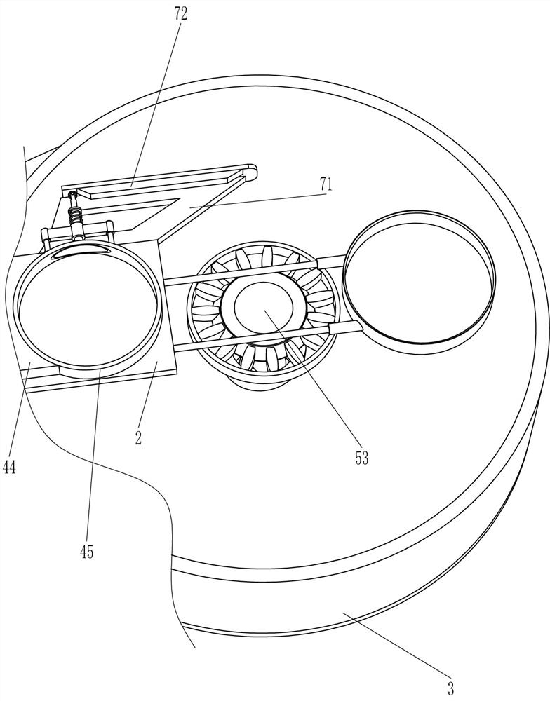
[0067] On the basis of Example 2, such as figure 1 , figure 2 , Figure 5 and Image 6 As shown, a fixing mechanism 7 is also included, and the fixing mechanism 7 includes a connecting frame 71, an oblique plate 72, a bracket 73, a guide ring 74, a second spring 75, a guide tube 76, a third spring 77, a slide bar 78 and a contact wheel 79, the right side rear part of the horizontal plate 2 is connected with a connecting frame 71, the rear side of the connecting frame 71 top is connected with a slanted plate 72, the rear side of the pushing ring 45 is connected with a support 73, and the middle of the support 73 is connected with a guide ring 74, and the guide ring 74 is connected with a conduit 76, a second spring 75 is connected between the rear side of the conduit 76 and the rear side of the guide ring 74, the second spring 75 is sleeved on the outside of the conduit 76, and the conduit 76 is slidably connected with a slide bar 78, the slide bar 78 Rear side rotation typ...
PUM
 Abstract
Description
Claims
Application Information
 - R&D
- Intellectual Property
- Life Sciences
- Materials
- Tech Scout
- Unparalleled Data Quality
- Higher Quality Content
- 60% Fewer Hallucinations
Browse by: Latest US Patents, China's latest patents, Technical Efficacy Thesaurus, Application Domain, Technology Topic, Popular Technical Reports.
© 2025 PatSnap. All rights reserved.Legal|Privacy policy|Modern Slavery Act Transparency Statement|Sitemap|About US| Contact US: help@patsnap.com


