Pitching transmission device and method for two paths of pitching loads based on infrared panoramic system

A transmission device and pitch motion technology, which is applied in the exploration of optical devices, supporting machines, mechanical equipment, etc., can solve the problems of reducing the anti-interference performance and detection accuracy of the system, increasing the volume of the infrared peripheral vision system, and increasing the manufacturing cost. Improve anti-interference performance, achieve integration, and reduce volume

Active Publication Date: 2021-01-22
TIANJIN JINHANG INST OF TECH PHYSICS
View PDF6 Cites 0 Cited by
  • Summary
  • Abstract
  • Description
  • Claims
  • Application Information

AI Technical Summary

Problems solved by technology

However, the two-way imaging system, two-way pitching components and two sets of drive motors need to be aligned for the splicing of the two fields of view, which will lead to a larger volume of the infrared peripheral vision system, which is not conducive to concealment during detection and reduces the anti-interference performance of the system and detection accuracy, and increase the manufacturing cost

Method used


Image

  • Pitching transmission device and method for two paths of pitching loads based on infrared panoramic system
  • Pitching transmission device and method for two paths of pitching loads based on infrared panoramic system
  • Pitching transmission device and method for two paths of pitching loads based on infrared panoramic system

Examples


Embodiment Construction

[0034] The present invention will be further described in detail below in conjunction with the accompanying drawings and embodiments. It should be understood that the specific embodiments described here are only used to explain related inventions, rather than to limit the invention. It should also be noted that, for ease of description, only parts related to the invention are shown in the drawings.

[0035] It should be noted that, in the case of no conflict, the embodiments of the present invention and the features in the embodiments can be combined with each other. The present invention will be described in detail below with reference to the accompanying drawings and examples.

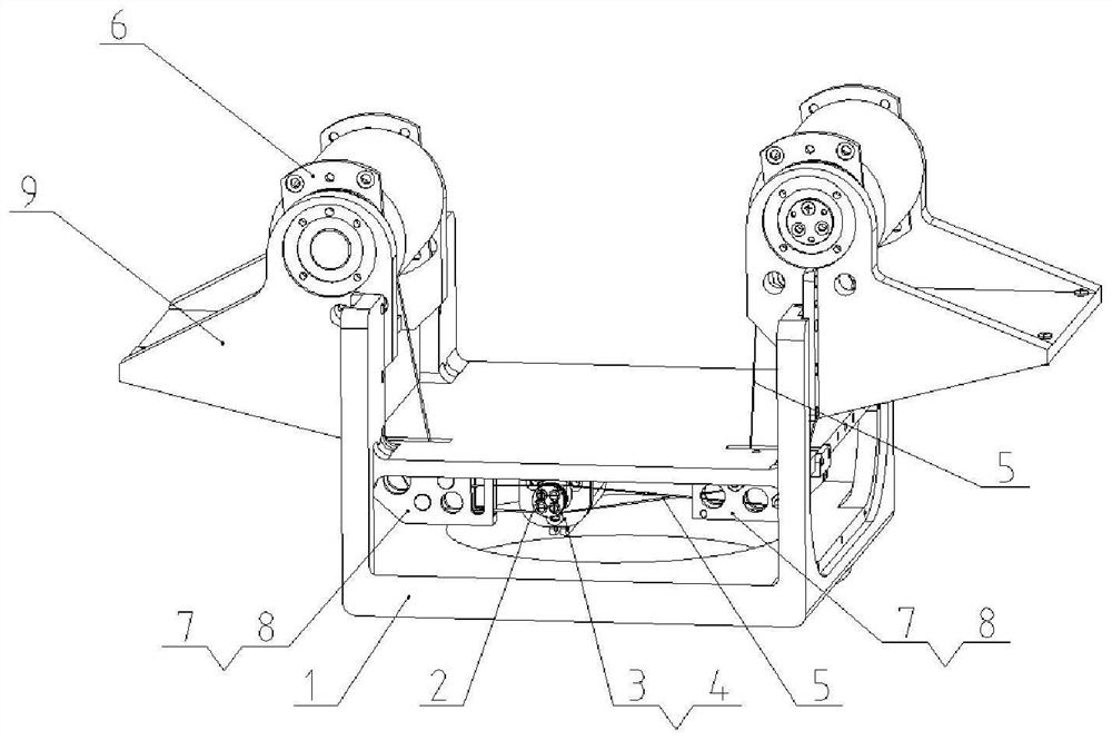
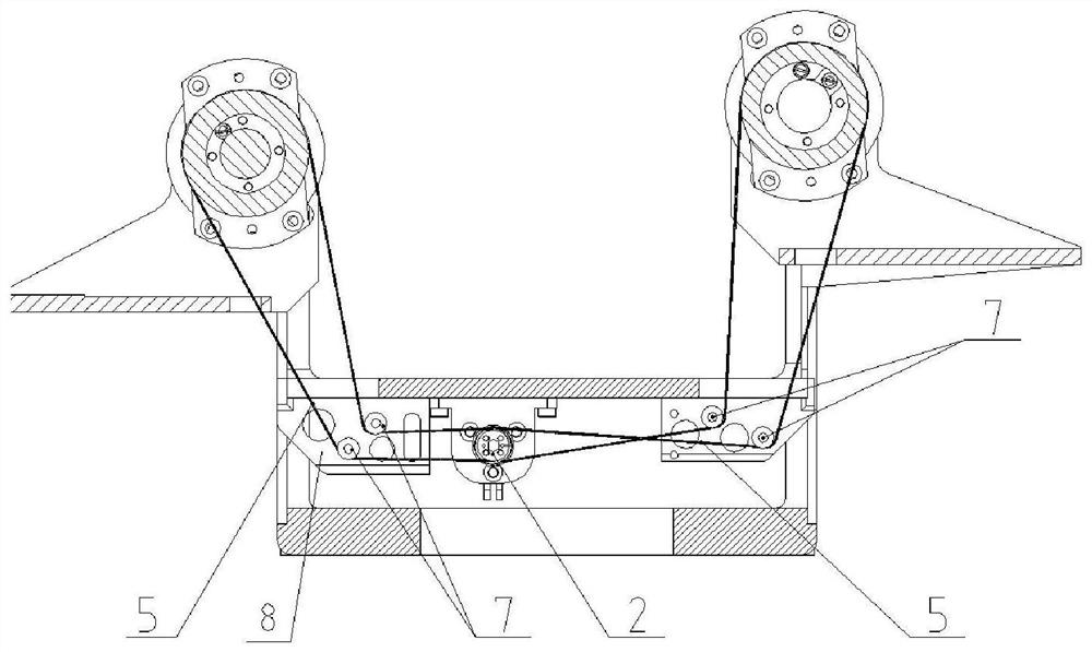
[0036] figure 1 It shows a three-dimensional view of the structure of the pitch transmission device of the two-way pitch load based on the infrared peripheral vision system provided by the embodiment of the present invention, figure 2 main view. The pitching transmission device provided by the e...


PUM


Abstract

The invention provides a pitching transmission device and method for two paths of pitching loads based on an infrared panoramic system. The pitching transmission device and method are used for solvingthe problems that when two paths of pitching components conduct synchronous transmission, the system size is large, the cost is high, and the anti-interference capacity is reduced. According to the pitching transmission device, a motor and a motor driving wheel are fixed to the middle of a fixing base, the two sides of the motor are each provided with a steel wire rope, pitching shafts at the twosides are driven to rotate, then a support and a load component which are fixed to the pitching shafts are driven to move synchronously, and therefore the effect that one motor drives two pitching mechanisms at the same time is achieved. Two paths of pitching transmission mechanisms are driven by one motor, and two paths of imaging systems in the pitching components of the infrared panoramic system are driven at the same time, so that smooth splicing of two fields of view is realized, the size of the infrared panoramic system is reduced, the space is saved, the anti-interference capacity of the system is improved, the detection precision is ensured, the cost is saved, and the integration, miniaturization and low cost of the infrared panoramic system with two paths of pitching loads are realized.

Description

technical field [0001] The invention belongs to the field of infrared detection equipment, and in particular relates to a pitch transmission device and a method for a two-way pitch load based on an infrared peripheral vision system. Background technique [0002] The infrared peripheral vision system is an imaging detection device that works in a passive manner. It detects objects within the surrounding field of vision through infrared imaging. It has good concealment, anti-electronic interference, high precision, good low-altitude detection performance, and a wide range of vision Large and many other advantages, it is an important part of photoelectric countermeasures. With the complexity and diversification of application scenarios, the infrared peripheral vision system has a development trend of integration, miniaturization, and low cost. [0003] In the prior art, in order to obtain a larger detection field of view, the infrared peripheral vision system includes an azimu...

Claims


Application Information

Patent Timeline
Patent Type & Authority Applications(China)
IPC IPC(8): F16M11/18F16M11/04F16M11/10F16M11/22G01V8/10
CPCF16M11/18F16M11/04F16M11/10F16M11/22G01V8/10Y02E10/72
Inventor 殷永亮张美生李秀明张宗房昊宇
Owner TIANJIN JINHANG INST OF TECH PHYSICS
Why Eureka
Try Eureka