Remote plasma conveying pipe and remote plasma processing equipment

A technology of remote plasma and conveying pipe, which is applied in the field of plasma processing equipment, and can solve the problems of lower yield of silicon wafers and generation of by-products, etc.

Pending Publication Date: 2021-01-22
INST OF MICROELECTRONICS CHINESE ACAD OF SCI +1
View PDF0 Cites 0 Cited by
  • Summary
  • Abstract
  • Description
  • Claims
  • Application Information

AI Technical Summary

Problems solved by technology

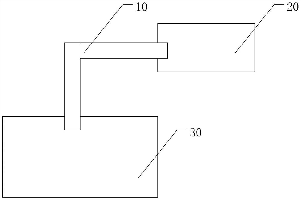
[0004] The purpose of the present invention is to provide a remote plasma delivery pipe and remote plasma processing equipment to solve the technical problem that the remote plasma is easy to react with the plasma delivery pipe to produce by-products, which leads to a decrease in the final yield of silicon wafers

Method used


Image

  • Remote plasma conveying pipe and remote plasma processing equipment
  • Remote plasma conveying pipe and remote plasma processing equipment
  • Remote plasma conveying pipe and remote plasma processing equipment

Examples


Embodiment Construction

[0023] Hereinafter, embodiments of the present disclosure will be described with reference to the drawings. It should be understood, however, that these descriptions are exemplary only, and are not intended to limit the scope of the present disclosure. Also, in the following description, descriptions of well-known structures and techniques are omitted to avoid unnecessarily obscuring the concepts of the present disclosure.

[0024] Various structural schematic diagrams according to embodiments of the present disclosure are shown in the accompanying drawings. The figures are not drawn to scale, with certain details exaggerated and possibly omitted for clarity of presentation. The shapes of the various regions and layers shown in the figure, as well as their relative sizes and positional relationships are only exemplary, and may deviate due to manufacturing tolerances or technical limitations in practice, and those skilled in the art will Regions / layers with different shapes, ...


PUM

PropertyMeasurementUnit
thicknessaaaaaaaaaa
thicknessaaaaaaaaaa

Abstract

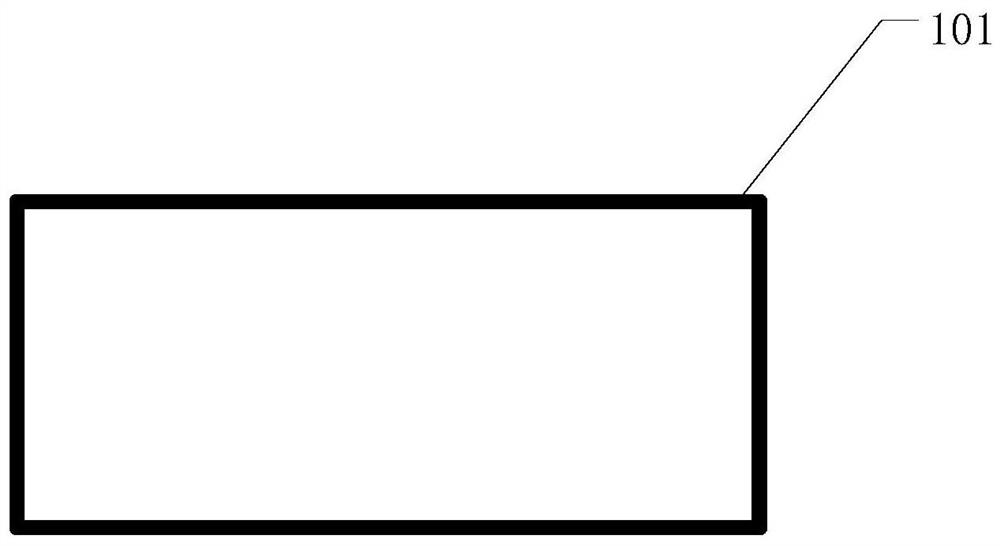
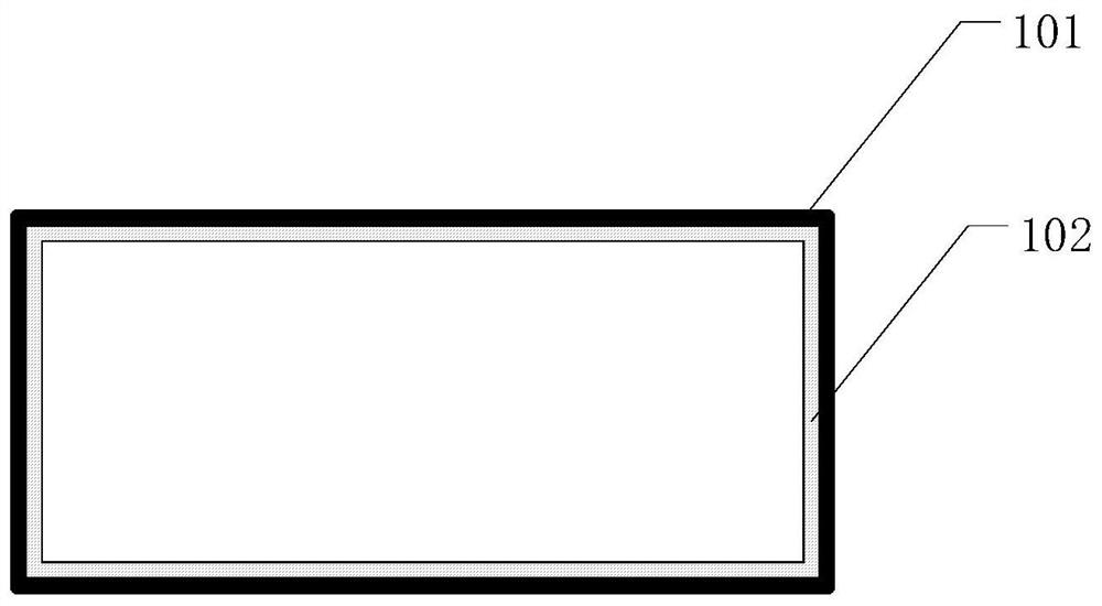
The invention discloses a remote plasma conveying pipe and remote plasma processing equipment, which relate to the technical field of plasma processing, and aim to solve the technical problem that thefinal yield of silicon wafers is reduced due to the fact that remote plasmas easily react with the plasma conveying pipe to generate byproducts. The remote plasma conveying pipe is used for conveyingremote plasma to a process cavity, the remote plasma conveying pipe comprises a metal pipe and a ceramic structure formed on the inner wall of the metal pipe, and the ceramic structure is used for isolating the metal pipe from the remote plasma. The remote plasma processing equipment comprises the remote plasma conveying pipe provided by the technical scheme.

Description

technical field [0001] The invention relates to the technical field of remote plasma processing, in particular to a remote plasma delivery pipe and remote plasma processing equipment. Background technique [0002] Currently, silicon wafers with oxides formed on their surfaces are usually treated with plasma processing equipment. The plasma treatment equipment includes a plasma generator for generating plasma, a process chamber for placing silicon wafers and performing plasma treatment on the silicon wafers, and a plasma conveying pipe between the plasma generator and the process chamber. The plasma delivery pipe is used to deliver the remote plasma generated by the plasma generator into the process chamber. [0003] Usually, the remote plasma is added with etching gas, and the plasma conveying pipe is a metal pipe. Remote plasmas tend to react with the plasma delivery tube, producing by-products that may travel with the plasma into the process chamber. When the by-product...

Claims


Application Information

Patent Timeline
Patent Type & Authority Applications(China)
IPC IPC(8): H01J37/32H01L21/67
CPCH01J37/32807H01J2237/334H01L21/67069
Inventor 金暻台白国斌高建峰王桂磊崔恒玮丁云凌
Owner INST OF MICROELECTRONICS CHINESE ACAD OF SCI
Why Eureka
Try Eureka