Combined bone fracture plate for orthopaedic trauma

A combined bone plate technology, applied in the direction of internal bone synthesis, external plate, fixer, etc., can solve the problems of adhesion of patients with screw holes, trauma of patients with bone plate removed, insufficient contact between bone plate and bone, etc. Achieve the effect of improving the actual use effect and reducing the overall quality

Inactive Publication Date: 2021-01-26
臧成
View PDF0 Cites 3 Cited by
  • Summary
  • Abstract
  • Description
  • Claims
  • Application Information

AI Technical Summary

Problems solved by technology

[0002] Bone plate is an internal fixation device for fractures with a hole in the shape of a plate. It is often used in conjunction with bone screws or bone wires clinically. It is divided into two types: ordinary bone plate and compression bone plate. According to different purposes, it can be made into strip shape, Y shape, L shape shape, T shape, etc., but in the prior art, the actual structure of the bone plate is fixed, so that patients with different body types need to replace the bone plate with different structural sizes, and for a small number of patients, it is also necessary to customize the bone plate of a specific size, so that the bone plate The actual use effect is not good, and due to the fixed structure, the existing bone plate cannot be implanted with multi-angle screws according to the actual situation during actual use, which leads to insufficient actual contact between the bone plate and the bone, affecting the normal function of the bone plate In addition, during the recovery process of the patient, the inside of the idle screw hole on the surface of the bone plate is likely to adhere to the patient's diseased part, and then it is easy to cause greater trauma to the patient when the bone plate is taken out

Method used


Image

  • Combined bone fracture plate for orthopaedic trauma
  • Combined bone fracture plate for orthopaedic trauma
  • Combined bone fracture plate for orthopaedic trauma

Examples


Embodiment 1

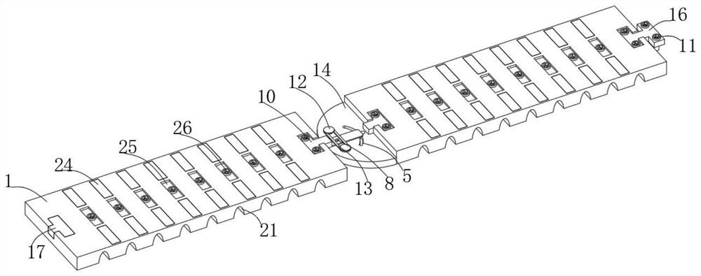
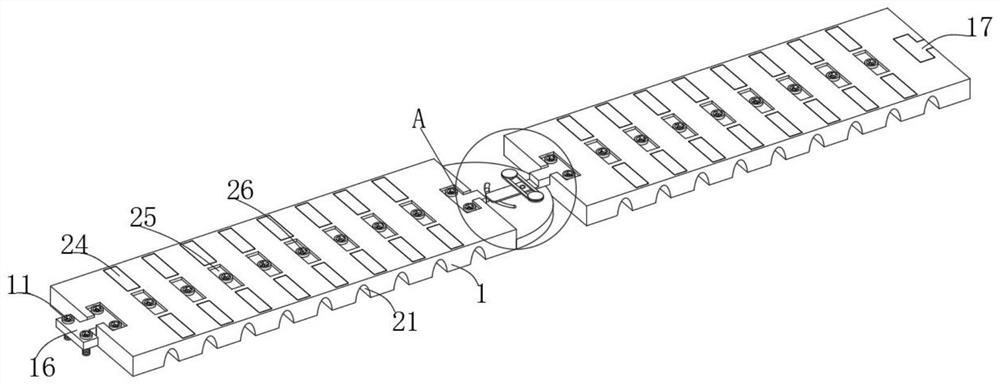
[0026] Embodiment one, with reference to Figure 1-8: A combined bone plate for orthopedic trauma, including a fixation plate 1, two fixation plates 1 are arranged in total, the establishment of the fixation plate 1 provides the installation basis for other functional parts of the equipment, and can effectively fix and support bones The bottom of each fixing plate 1 is equidistantly provided with a plurality of fitting grooves 21 along the horizontal direction. The establishment of the fitting grooves 21 enables the fixing plate 1 to be bent to a certain extent, thereby enabling the fixing plate 1 to better fit the patient. Bones, the top of each fixed plate 1 is equidistantly provided with three groups of limiting grooves 19 along the horizontal direction. There are seven positioning slots 19 in total, of which two sets of limiting slots 19 are slide-embedded with supporting pieces 25, and the establishment of the supporting pieces 25 enables the fixing bolts 26 to drive the ...

Embodiment 2

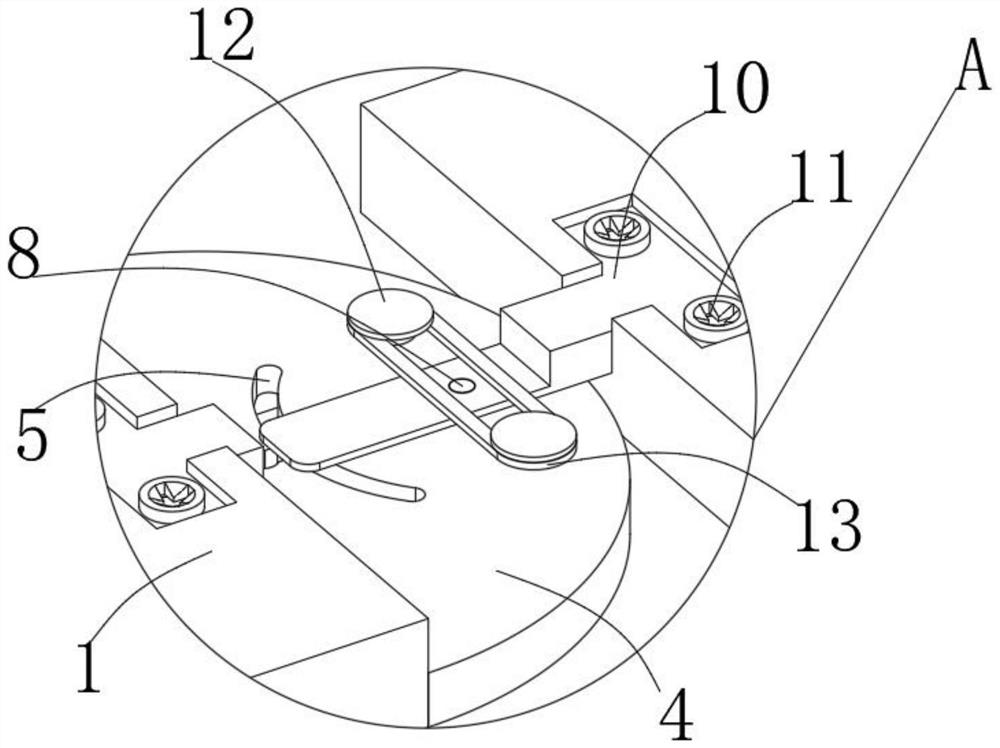
[0027] Embodiment two, refer to Figure 1-8 The bottom ends of a plurality of fixing bolts 26 pass through the corresponding connecting holes 23, and the bottom ends of each fixing bolt 26 extend to the bottom of the fixing plate 1. The establishment of this structure enables the fixing bolts 26 to effectively drive the fixing plate 1 to be close to the patient's bone , the bottom of the limit frame 13 is attached to the top of the connecting plate 10, the top of the limit frame 13 is attached to the inner top surface of the two limit bolts 12, the inside of the adjustment groove 7 is connected to the inside of the chute 5, and the inside of the adjustment groove 7 is connected to the placement groove 6 is internally connected. Through the establishment of this structure, the limit frame 13 can effectively squeeze and fix the position of the connecting plate 10. The bottom of the connecting plate 10 is located inside the chute 5 and is fixedly connected to the limit rod 15. The...

Embodiment 3

[0028] Embodiment three, refer to Figure 1-8 : The top of the connecting plate 10 near the center of the edges on both sides slides through the positioning bolts 11, the setting of the positioning bolts 11 cooperates with the first threaded hole 3 to facilitate the stable connection between other functional parts of the equipment and the fixing plate 1, and the bottom of the two positioning bolts 11 Both ends extend to the inside of the corresponding first threaded hole 3, and each positioning bolt 11 is screwed to the corresponding first threaded hole 3, and the top of the combination block 16 near the four corners also slides through the positioning bolts 11, and two of them The bottom ends of each positioning bolt 11 extend to the inside of the corresponding first threaded hole 3, and the two positioning bolts 11 are screwed to the corresponding first threaded hole 3, and the top of the bottom plate 4 near the two corners also slides through the positioning bolts 11. , and...


PUM


Abstract

The invention discloses a combined bone fracture plate for orthopaedic trauma. The combined bone fracture plate comprises two fixing plates; a plurality of attaching grooves are formed in the bottom of each fixing plate in the horizontal direction at equal intervals; three sets of limiting grooves are formed in the top of each fixing plate in the horizontal direction at equal intervals, and sevenlimiting grooves are formed in each set, wherein supporting pieces are embedded in the two sets of limiting grooves in a sliding mode; and a fixing bolt penetrates through the center of the top of each supporting piece in a sliding mode. According to the combined bone fracture plate, through combination blocks and positioning bolts, the multiple fixing plates can be stably connected in cooperationwith connecting grooves in the two sides of the tops of the fixing plates, the structure of the device can be conveniently adjusted according to the body types of patients, the device can meet the actual requirements of the patients with different body types, and the actual using effect of the device is improved; and through a connecting plate and a bottom plate, the connecting plate can be rotationally adjusted with a rotating shaft as the rotating center under the position limitation of limiting rods and sliding grooves.

Description

technical field [0001] The invention belongs to the technical field of medical equipment, in particular to a combined bone plate for orthopedic trauma. Background technique [0002] Bone plate is an internal fixation device for fractures with a hole in the shape of a plate. It is often used in conjunction with bone screws or bone wires clinically. It is divided into two types: ordinary bone plate and compression bone plate. According to different purposes, it can be made into strip shape, Y shape, L shape shape, T shape, etc., but in the prior art, the actual structure of the bone plate is fixed, so that patients with different body types need to replace the bone plate with different structural sizes, and for a small number of patients, it is also necessary to customize the bone plate of a specific size, so that the bone plate The actual use effect is not good, and due to the fixed structure, the existing bone plate cannot be implanted with multi-angle screws according to th...

Claims


Application Information

Patent Timeline
Patent Type & Authority Applications(China)
IPC IPC(8): A61B17/80A61B17/86
CPCA61B17/8023A61B17/8047A61B17/808A61B17/86
Inventor 臧成段丽娜
Owner 臧成
Why Eureka
Try Eureka