Classification treatment device for construction waste

A treatment device and technology for construction waste, which is applied in the direction of solid separation, separation of solids from solids with airflow, and filtration and screening, can solve the problems of large manpower assistance, low efficiency of construction waste, inconvenient collection, etc., and achieve complete separation, Ease of collection and prevent clogging

Active Publication Date: 2021-01-26
瑞泰环保装备有限公司
View PDF10 Cites 2 Cited by
  • Summary
  • Abstract
  • Description
  • Claims
  • Application Information

AI Technical Summary

Problems solved by technology

[0005] In order to overcome the disadvantages of low efficiency in processing construction waste in the prior art, requiring a large amount of manpower assistance and being inconvenient to collect, the technical problem of the present invention is to provide a construction waste sorting and processing device that is easy to operate, high in classification efficiency and easy to collect to solve the current problem. There are technical problems

Method used


Image

  • Classification treatment device for construction waste
  • Classification treatment device for construction waste
  • Classification treatment device for construction waste

Examples


Embodiment 1

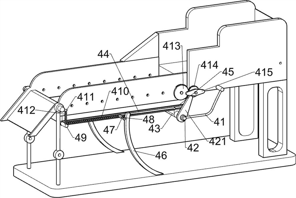
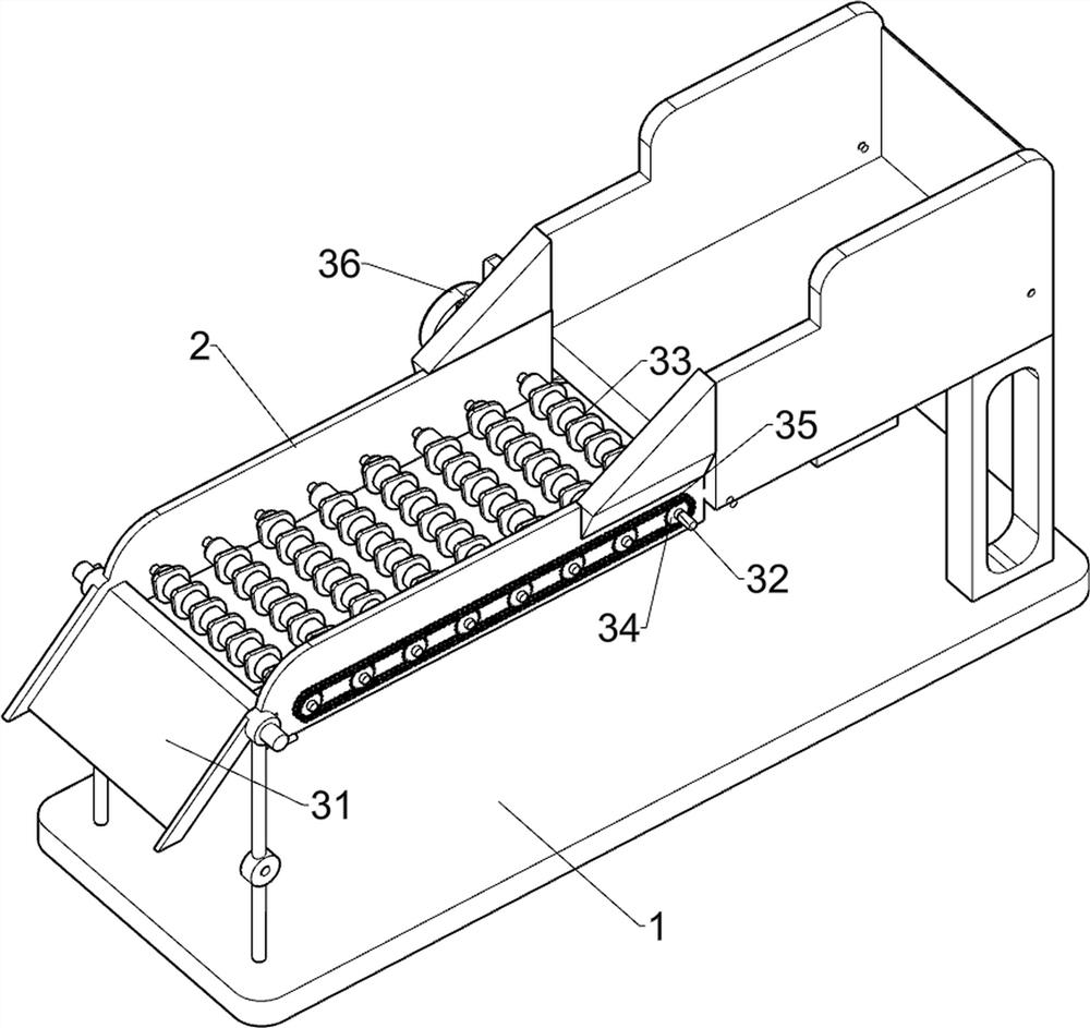
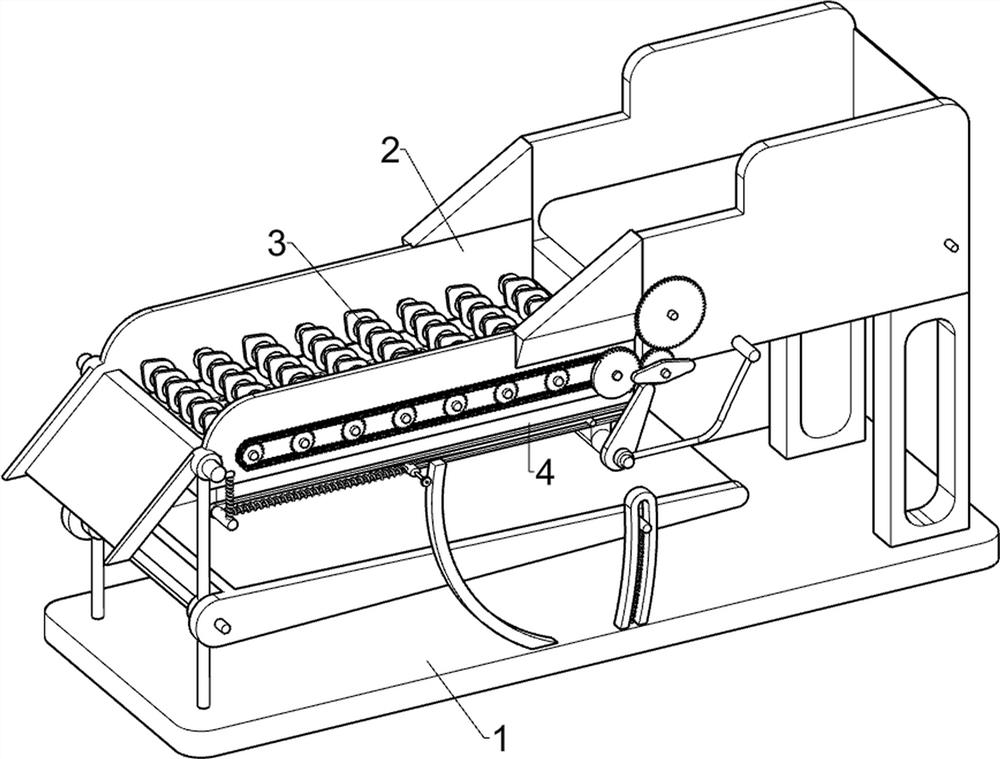
[0022] A sorting device for construction waste, such as figure 1 , figure 2 and image 3 As shown, it includes a bottom plate 1, a frame 2, a separation mechanism 3 and a screening mechanism 4. The fixed connector on the top of the bottom plate 1 has a frame 2, and a separation mechanism 3 is arranged between the left part of the frame 2. The bottom plate 1 and the frame 2 There is a screening mechanism 4 in between.

[0023] When people need to use this device, first people pour the construction waste on the separation mechanism 3, then place the collection tools under the screening mechanism 4 and on the left side of the frame 2, and then start the separation mechanism 3, and the separation mechanism 3 operates Drive the larger construction waste on it to move to the left, and make the smaller construction waste fall into the screening mechanism 4. When the larger construction waste is driven to move to the leftmost side of the frame 2, the larger construction waste The ...

Embodiment 2

[0029] On the basis of Example 1, such as Figure 4 and Figure 5 Shown, also comprise second connecting rod 5, cylinder 6, second circular gear 7 and transmission belt 8, frame 2 right side is symmetrically provided with second connecting rod 5 in the mode of rotation, on the second connecting rod 5 Both are fixedly connected with a drum 6, and the front end of the second connecting rod 5 on the left side is provided with a second circular gear 7, the second circular gear 7 meshes with the first circular gear 414, and a transmission belt 8 is wound between the drums 6.

[0030] First, people pour construction waste on the conveyor belt 8, and when the first circular gear 414 rotates, the first circular gear 414 drives the second circular gear 7 to rotate counterclockwise, and the second circular gear 7 drives the second connecting rod 5 to rotate counterclockwise , the second connecting rod 5 drives the conveyor belt 8 to rotate counterclockwise through the roller 6, and the...


PUM


Abstract

The invention relates to a treatment device, in particular to a classification treatment device for construction waste. The classification treatment device for construction waste is convenient to operate, high in classification efficiency and convenient for collecting, and then the problems existing in the prior art are solved. The classification treatment device for construction waste comprises abottom plate, a separation mechanism and a screening mechanism, wherein racks are arranged on the bottom plate; the separation mechanism is arranged between the racks; and the screening mechanism isarranged between the bottom plate and the racks. By starting a servo motor, rotation of first rotating rods is realized, then rotation of rotating blocks and left-right movement of a screening frame are carried out at the same time through cooperation of the separation mechanism and the screening mechanism, and thus the classification of construction waste is facilitated; and the screening frame continuously moves left and right, so that circular blocks continuously extrude arc-shaped blocks, then the vibration of the screening frame can be realized, and thus the screening frame is prevented from being blocked.

Description

technical field [0001] The invention relates to a processing device, in particular to a construction waste classification processing device. Background technique [0002] Construction waste refers to the dregs, waste materials, silt and other wastes generated during the laying, demolition and repair of buildings. These wastes are collectively referred to as construction waste. [0003] These construction wastes are of no help to the building itself, but they are substances produced during the construction process, which need to be dealt with accordingly. After sorting and screening, many wastes in the garbage can be reused as renewable resources, such as: scrap steel bars, scrap iron wires and various scrap steel accessories and other metals, which can replace sand and be used for plastering mortar and concrete cushion, etc. It can also be used to make building material products such as paving bricks and lattice bricks, but the existing technology is cumbersome and ineffici...

Claims


Application Information

Patent Timeline
Patent Type & Authority Applications(China)
IPC IPC(8): B07B9/00B07B1/28B07B1/42B07B1/46B07B1/14
CPCB07B9/00B07B1/30B07B1/42B07B1/46B07B1/14Y02W30/58
Inventor 陈春艳
Owner 瑞泰环保装备有限公司
Why Eureka
Try Eureka