
Full-automatic pot handle assembling device

An assembly device and fully automatic technology, applied in auxiliary devices, auxiliary welding equipment, welding/cutting auxiliary equipment, etc., can solve problems such as low welding firmness, cumbersome heating process, and leakage of riveting positions, and achieve good welding results , convenient and fast brazing, high welding strength effect

Pending Publication Date: 2021-01-26
SUZHOU JIAYI STAINLESS STEEL PROD
View PDF6 Cites 0 Cited by
  • Summary
  • Abstract
  • Description
  • Claims
  • Application Information

AI Technical Summary

Problems solved by technology

The riveting method needs to be done after drilling holes at the connection position between the handle and the pot body. There are many connection steps. At the same time, after the connection, there will be riveted assembly protrusions on the inner edge of the pot body. At the same time, the riveting position is prone to leakage and other problems.
However, the traditional welding needs to use flames for high-temperature heating, the heating process is more cumbersome, and the flame needs to be aligned, which needs to be done manually, the efficiency is low, and the welding effect is poor, and the traditional pot handle welding is usually done At the joint joint between the pot handle and the pot body, there are fewer welding contact points, and strips are required for edge sealing. The welding process is longer and the welding firmness is lower.

Method used


Image

  • Full-automatic pot handle assembling device
  • Full-automatic pot handle assembling device
  • Full-automatic pot handle assembling device

Examples


Embodiment Construction

[0015] Below in conjunction with embodiment the present invention is further described:

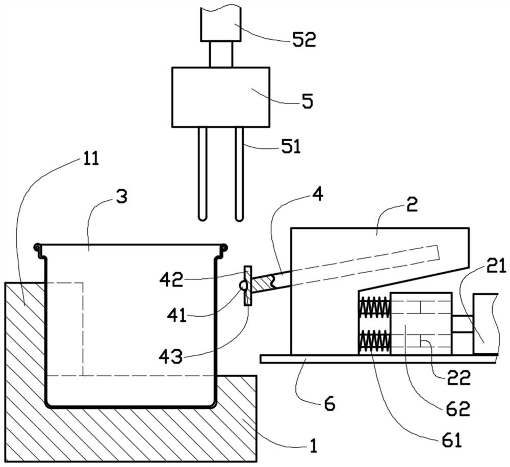
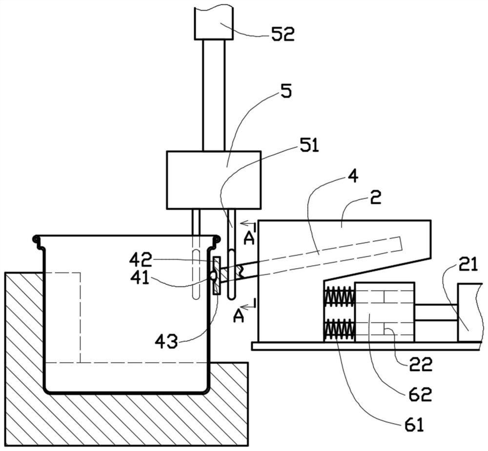
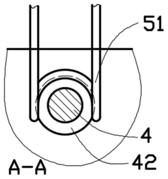
[0016] Such as figure 1 , figure 2 with image 3 As shown in the embodiment, the fully automatic pot handle assembly device includes a pot base 1 and a handle mold 2. The pot body 3 to be processed is placed on the pot base 1, and the pot base 1 limits the left and right sides of the pot body 3. Assembled, the handle part of the pot handle 4 is assembled in the handle mold 2, and the specific structure of the mold 2 is specifically designed according to the handle 4. During assembling, the welding position of the handle 4 of the pot stretches out toward the position of the pot body 3 on the right, and the connection position of the handle 4 of the pot is facing the position to be welded of the pot body 3. The rear portion of the handle mold 2 is equipped with a push module 21 that can push the handle mold 2 together with the pot handle 4 left and right. The position to be welded of th...


PUM


Abstract

The invention provides a full-automatic pot handle assembling device. The full-automatic pot handle assembling device comprises a pot base and a handle mold, wherein a to-be-machined pot body is placed on the pot base, a holding part of a pot handle is assembled in the handle mold, the connecting position of the pot handle is right opposite to the to-be-welded position of the pot body, a drill rodblock is embedded into the to-be-welded position of the pot handle, the melting point of the drill rod block is lower than that of the welding position of the pot handle and the pot body, a high-frequency welding head extending downwards is assembled above the welding position of the pot body, the pot handle and the pot body are elastically ejected at the to-be-welded position through the drill rod block, an alternating high-frequency magnetic field is generated on the high-frequency welding head in a welding process to melt the drill rod block between the pot handle and the pot body, the welding position of the pot handle is elastically pushed out to the surface of the pot body, and the welding position is filled with the molten drill rod block, the high-frequency current of a high-frequency welding module is closed, and welding is completed. The device can automatically, quickly and comprehensively weld the contact position of the pot body and the pot handle.

Description

technical field [0001] The invention relates to the technical field of pot processing, in particular to a fully automatic pot handle assembly device. Background technique [0002] Pots are usually used for cooking food. For the convenience of taking the pots, pot handles are usually installed on the pots. Traditional pot handles are usually connected by means of riveting, welding and the like. The riveting method needs to be carried out after drilling holes at the connection position between the handle and the pot body. There are many connection steps. At the same time, after the connection, there will be riveted assembly protrusions on the inner edge of the pot body. At the same time, the riveting position is prone to leakage and other problems. However, the traditional welding needs to use flames for high-temperature heating, the heating process is more cumbersome, and the flame needs to be aligned, which needs to be done manually, the efficiency is low, and the welding e...

Claims


Application Information

Patent Timeline
Patent Type & Authority Applications(China)
IPC IPC(8): B23K3/00B23K3/08B23K1/002B23K37/04
CPCB23K1/002B23K3/00B23K3/08B23K3/087
Inventor 殷林根
Owner SUZHOU JIAYI STAINLESS STEEL PROD
Learn More