
High-damping sliding energy dissipation limiting simple bridge seismic resistance check block device

A high-damping, simple technology, applied to bridges, bridge parts, bridge materials, etc., can solve problems such as difficult repair, direct shear damage, main beam and pier damage, etc., to prolong service life, protect bridges, and reduce damage Effect

Pending Publication Date: 2021-01-26
NANCHANG UNIV
View PDF0 Cites 0 Cited by
  • Summary
  • Abstract
  • Description
  • Claims
  • Application Information

AI Technical Summary

Problems solved by technology

Because it is a reinforced concrete structure with low toughness and high rigidity, once a large earthquake occurs, it is prone to direct shear failure, which can easily cause damage to the main beam and pier
Since it is a reinforced concrete structure, it is not easy to repair when damaged
In view of the advantages and disadvantages of the above-mentioned traditional anti-seismic stoppers, it is necessary to design a highly multi-directional limiter, which can limit even small displacements and vertical displacements; it also has buffer energy consumption, which can limit large displacements of bridges at the same time. A device that reduces damage to itself

Method used


Image

  • High-damping sliding energy dissipation limiting simple bridge seismic resistance check block device
  • High-damping sliding energy dissipation limiting simple bridge seismic resistance check block device
  • High-damping sliding energy dissipation limiting simple bridge seismic resistance check block device

Examples


Embodiment Construction

[0026]The present invention will be further explained below:

[0027]SeeFigure 1-7,

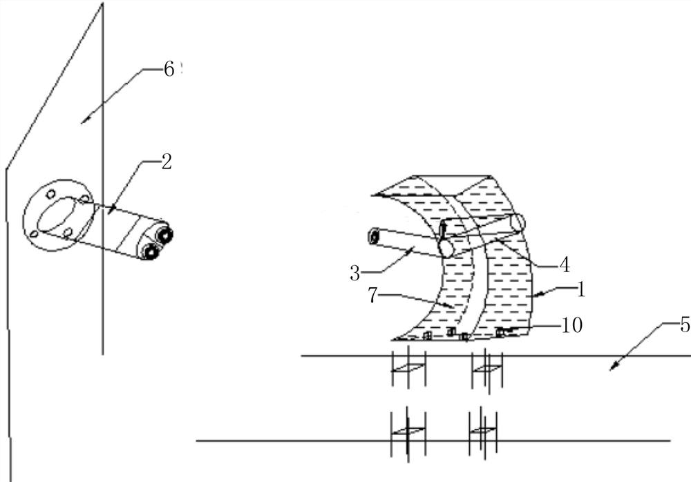
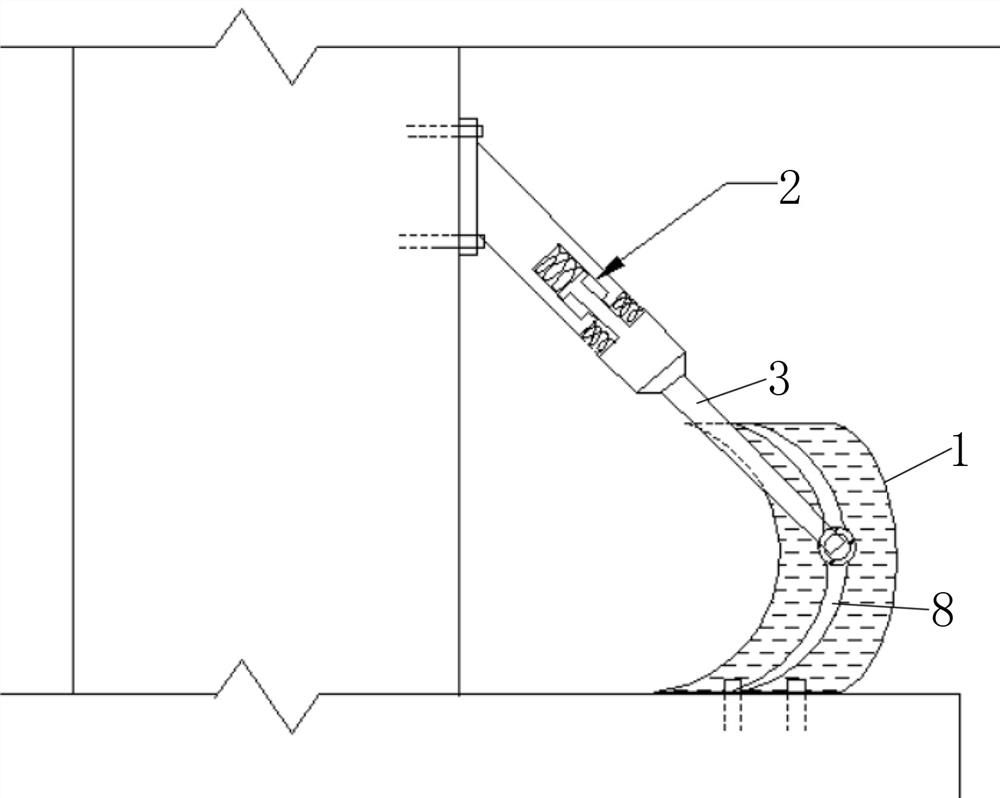
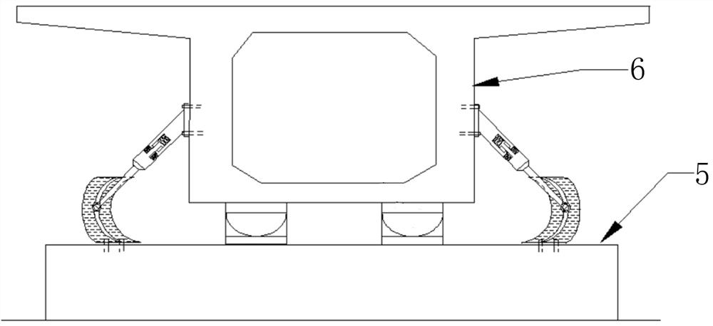
[0028]The invention discloses a high-damping sliding energy-consuming simple bridge seismic stop device, which comprises an arc-shaped block 1, a Y-shaped iron rod 2, a connecting rod 3, and a sliding rod 4. The arc-shaped block 1 is The arc-shaped hollow structure, the bottom of which is fixed on the top of the pier 5, the front and rear side walls of which are arc-shaped limiting plates protruding away from the main girder 6, and the inner cavity is filled with high-damping energy dissipation cushions 7. The high-damping energy-consuming cushion 7 is formed with a sliding cavity 8 along the vertical direction for one end of the sliding rod 4 to slide, and the other end of the sliding rod 4 is between the Y-shaped iron rod 2. They are connected by a connecting rod 3; the top end of the Y-shaped iron rod 2 is hinged to the side wall of the main beam 6.

[0029]The Y-shaped iron rod 2 includes a sleeve 21 an...


PUM


Abstract

The invention relates to the technical field of bridge seismic resistance, in particular to a high-damping sliding energy dissipation limiting simple bridge seismic resistance check block device whichcomprises an arc-shaped check block, a Y-shaped iron rod, a connecting rod and a sliding rod, the arc-shaped check block is of an arc-shaped hollow structure, and the bottom of the arc-shaped check block is fixed to the top of a pier; the front side wall and the rear side wall of the sliding rod are arc-shaped limiting plates protruding in the direction away from a main beam, an inner cavity of the sliding rod is filled with a high-damping energy dissipation buffering cushion, a sliding cavity used for allowing one end of the sliding rod to slide is formed in the high-damping energy dissipation buffering cushion in the vertical direction, and the other end of the sliding rod is connected with the Y-shaped iron rod through a connecting rod; and the top end of the Y-shaped iron rod is hinged with the side wall of the main beam. Multi-directional displacement of the main beam can be limited, kinetic energy of the main beam is converted into internal friction heat energy through the device, and therefore the effect of reducing damage is achieved.

Description

Technical field[0001]The invention relates to the technical field of bridge earthquake resistance, in particular to a high damping sliding energy consumption limit simple bridge earthquake resistance block device.Background technique[0002]I have experienced rapid development in the transportation industry, with hundreds of thousands or even millions of bridges rising from the ground. Earthquakes are the biggest nemesis of bridges. Earthquakes can cause many problems with bridges, such as lateral displacement of bridges, especially the upper part of the bridge. When the lateral displacement is too large, the main beam will be misaligned or even overturned. Bridges are expensive to build. Once the irreversible bridge overturns occurs, the loss of economic value is huge. In order to reduce the damage to the bridge due to earthquakes, at the beginning of the construction of the bridge, seismic blocks are usually installed at the piers and cap beams, and the structural functions of the s...

Claims


Application Information

Patent Timeline
Patent Type & Authority Applications(China)
IPC IPC(8): E01D19/00E01D101/30
CPCE01D19/00E01D2101/30
Inventor 田钦陈小钢李顺治樊霖涛
Owner NANCHANG UNIV
Learn More