Light concrete cast-in-place robot

A light-weight concrete and robot technology, applied in construction, building structure, and building material processing, can solve problems such as low technical content, large machinery, and limited precision, and achieve high flexibility and precision, and construction rhythm Compact, highly mechanized effect

Active Publication Date: 2021-01-26
TONGJI UNIV
View PDF9 Cites 3 Cited by
  • Summary
  • Abstract
  • Description
  • Claims
  • Application Information

AI Technical Summary

Problems solved by technology

[0003] 1. Low manpower utilization efficiency: Generally speaking, although the feeding pipe can be remotely controlled, the mechanical position is high and the accuracy is limited. It still needs one or more workers to hold the feeding pipe to make the concrete pour to the correct position; one The vibrating machine requires a worker to perform continuous and repeated operations, but the technical content is not too high; the surface can be plastered with a surface machine, but the surface machine is also used by the worker, and sometimes multiple workers are required to work together
[0004] 2. The accuracy of plastering is limited: When workers plaster the surface, the thickness of the plastering surface is determined by the on-site elevation indication. The indicator can be a line or a vertical mark, but this still needs to rely on the experience of the worker to control the accuracy
[0005] 3. The traditional mechanized equipment is too large: there are also automatic vibrators and automatic plastering machines on the market, but these machines are placed on both sides of the road with a large shelf, and then multiple vibrators or large plasters are used. For integral construction, once the road surface is very wide, this kind of machinery will be very large. If it is constructed on the bridge surface, it will be difficult to lift and transport, and it cannot handle special parts such as manholes.

Method used


Image

  • Light concrete cast-in-place robot
  • Light concrete cast-in-place robot
  • Light concrete cast-in-place robot

Examples


Embodiment

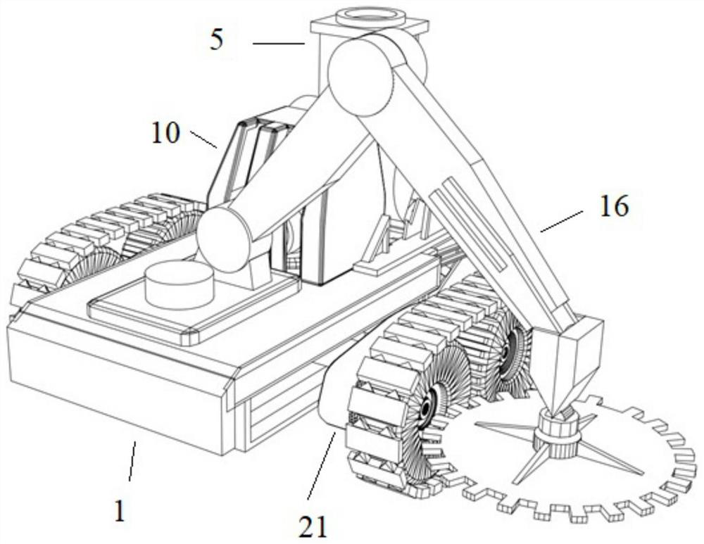
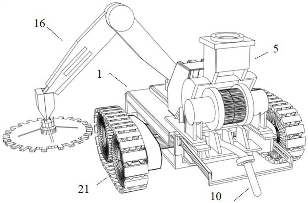
[0047] like figure 1 , 2 As shown, a light-duty concrete cast-in-place robot, the cast-in-place robot includes a vehicle body 1, a motion system 21, a blanking system 5, a vibrating system 10, a plastering system 16 and a motor system 21, a blanking system 5, and a vibrating system respectively. 10 and the plastering system 16 are electrically connected to the control system, the motion system 21 is arranged at the bottom of the vehicle body 1, the unloading system 5, the vibrating system 10 and the plastering system 16 are all arranged on the vehicle body 1, and the unloading system 5 includes a concrete The lower material cylinder 6 of the channel, the bottom of the lower material cylinder 6 is provided with a concrete discharge port 601 opening to the rear of the vehicle body 1, the vibrating system 10 includes a vibrating rod 11 that can be lifted and positioned at the rear of the vehicle body 1, and the plastering system 16 includes a The multi-degree-of-freedom surface ...


PUM


Abstract

The invention relates to a light concrete cast-in-place robot, the cast-in-place robot comprises a vehicle body, a motion system, a discharging system, a vibrating system, a plastering system and a control system electrically connected with the motion system, the discharging system, the vibrating system and the plastering system, the motion system is arranged at the bottom of the vehicle body, thedischarging system, the vibrating system and the plastering system are all arranged on the vehicle body, the discharging system comprises a discharging cylinder internally provided with a concrete channel, the bottom of the discharging cylinder is provided with a concrete discharging port with an opening towards the rear portion of the vehicle body, the vibrating system comprises a vibrating rodwhich can ascend and descend and is located on the rear portion of the vehicle body, the plastering system comprises a plastering device with multiple degrees of freedom, and the plastering device islocated on one side of the vehicle body. Compared with the prior art, the light concrete cast-in-place robot has the advantages that concrete discharging, vibrating and plastering can be conducted atthe same time, light weight and flexibility are achieved, traditional manual labor is replaced, and the construction mechanization degree is improved.

Description

technical field [0001] The invention belongs to the field of concrete cast-in-place construction, and in particular relates to a light concrete cast-in-place robot. Background technique [0002] The traditional concrete cast-in-place construction scheme mainly has the following problems: [0003] 1. Low manpower utilization efficiency: Generally speaking, although the feeding pipe can be remotely controlled, the mechanical position is high and the accuracy is limited. It still needs one or more workers to hold the feeding pipe to make the concrete pour to the correct position; one The vibrating machine requires a worker to perform continuous and repeated operations, but the technical content is not too high; the surface can be plastered with a plastering machine, but the plastering machine is also used by workers, and sometimes multiple workers are required to work together. [0004] 2. The accuracy of plastering is limited: When workers plaster the surface, the thickness o...

Claims


Application Information

Patent Timeline
Patent Type & Authority Applications(China)
IPC IPC(8): E04G21/04E04G21/06E04G21/08E04F21/24
CPCE04G21/0436E04G21/0445E04G21/066E04G21/08E04F21/245
Inventor 罗钊辉温欣毕力天林宇航周子越邹德明屈宏雅
Owner TONGJI UNIV
Why Eureka
Try Eureka