Forming and winding equipment for capacitor shell processing

A technology for capacitors and shells, which is applied in the field of forming and winding equipment for capacitor shell processing. It can solve the problems of poor effect and low winding efficiency of aluminum sheets, and achieve the effects of convenient use, effective and stable heating, winding and shaping, and improved continuity.

Active Publication Date: 2022-02-18
铜陵隆顺科技有限公司
View PDF9 Cites 0 Cited by
  • Summary
  • Abstract
  • Description
  • Claims
  • Application Information

AI Technical Summary

Problems solved by technology

[0004] The purpose of the present invention is to solve the problem of low winding efficiency and poor effect of aluminum sheets in the installation of capacitor casings in the prior art, and propose a forming and winding equipment for capacitor casing processing

Method used


Image

  • Forming and winding equipment for capacitor shell processing
  • Forming and winding equipment for capacitor shell processing
  • Forming and winding equipment for capacitor shell processing

Examples


Embodiment 1

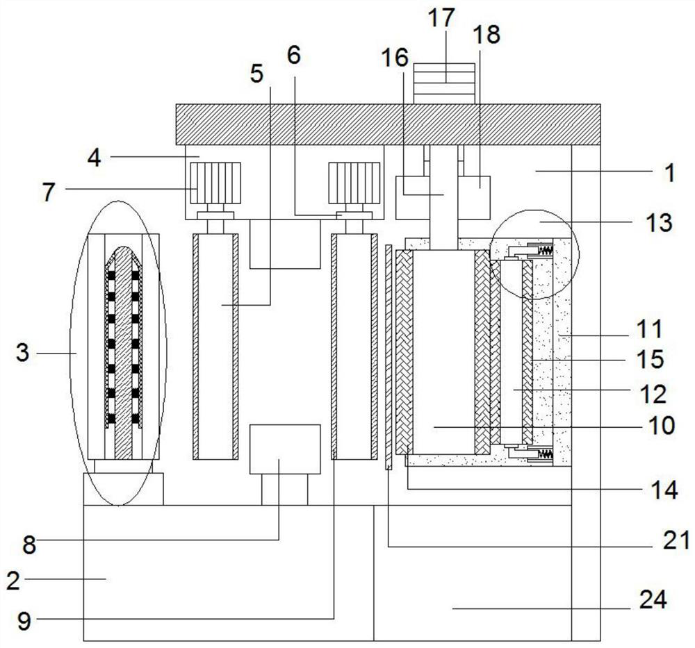
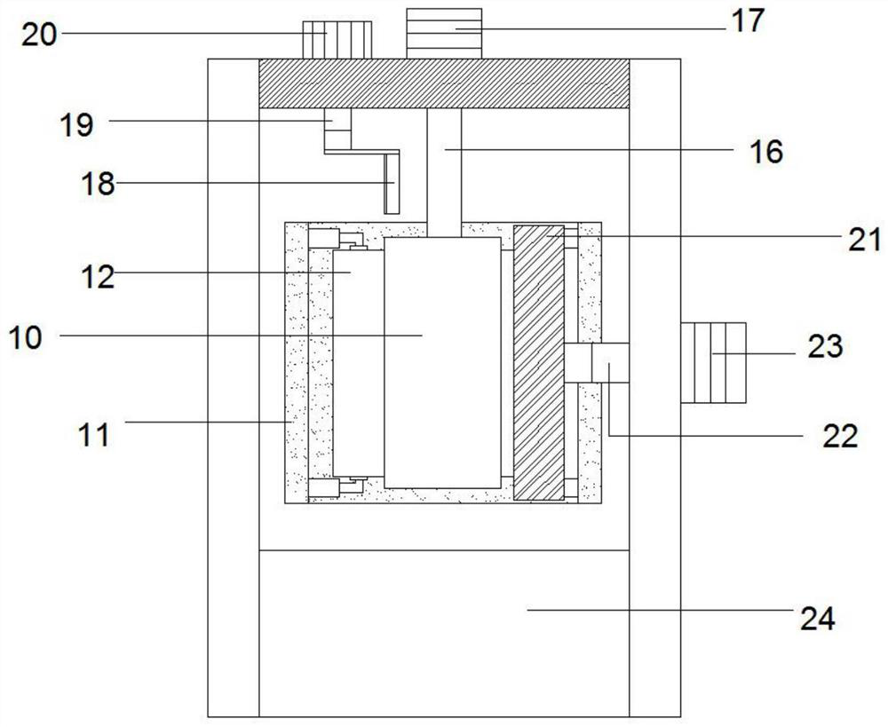
[0031] refer to Figure 1-6 , a forming and winding equipment for capacitor casing processing, comprising a winding box 1, a base 2 below the winding box 1, a placement mechanism 3 on the left side of the winding box 1 and a winding roller 10 on the right side of the winding box 1, The placement mechanism 3 is arranged above the left side of the base, and a winding shaft 31 is placed on the placement mechanism 3, a first heating layer 14 is arranged outside the winding roller 10, and a U-shaped heating layer 14 is arranged on the right side of the winding roller 10. Protective plate 11, the outer side of U-shaped protective plate 11 is connected with the side wall of winding box 1, and the inside of U-shaped protective plate 11 is connected with the surface of winding roller 10 through a plurality of sizing rollers 12, and the upper and lower ends of sizing roller 12 are connected with U The connecting mechanism 13 arranged inside the protective plate 11 is connected in rotati...

Embodiment 2

[0037] like Figure 1-6 As shown, this embodiment is basically the same as Embodiment 1. Preferably, the placement mechanism 3 includes a rotating block 32 that is rotatably connected above the base 2, and a fixed column 28 that is fixedly connected above the rotating block 32. The winding shaft 31 It is sleeved on the outside of the fixing column 28 . It can effectively and conveniently fix the aluminum coil and improve the stability of the aluminum coil.

[0038]In order to further fix the winding shaft 31 and improve the stability, preferably, a bent plate 29 is arranged symmetrically on both sides of the outside of the fixed column 28, the upper end of the bent plate 29 is connected to the top of the fixed column 28, and the lower end is connected to the top of the fixed column 28. It extends toward the lower end of the fixed column 28 , and the bent plate 29 is connected to the fixed column 28 through a plurality of connecting springs 30 .

Embodiment 3

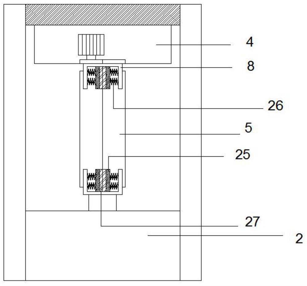
[0040] like Figure 1-6 As shown, this embodiment is basically the same as Embodiment 1. Preferably, two sets of guide rollers 5 are arranged inside the winding box 1 , and the two sets of guide rollers 5 are symmetrically arranged on the left and right sides of the U-shaped guide plate 8 . Effectively improve the stability of aluminum strip transmission.

[0041] In order to further improve the stability of the aluminum strip during the transmission process and at the same time enhance the safety of the device, preferably, a protective box 4 is provided on the left side of the lower end of the top of the winding box 1, and the upper end of the guide roller 5 passes through the protective box 4 It is connected with the rotating gear 6, and the rotating gear 6 between the two guide rollers 5 of each group meshes with each other, and one of the guide rollers 5 passes through the rotating gear 6 and is connected to the first motor 7 inside the winding box 1 , and the U-shaped gu...


PUM


Abstract

The invention discloses forming and winding equipment for processing capacitor shells, and relates to the technical field of capacitor shell processing. It includes a winding box, a base, a placement mechanism and a winding roller. A circle of the first heating layer is arranged outside the winding roller, and a U-shaped protective plate is arranged on the right side of the winding roller. The surface of the winding roller is slidingly connected, the upper end of the winding roller is connected with the second motor through the rotating shaft, a set of U-shaped guide plates is arranged between the placement mechanism and the winding roller, and extrusion plates are symmetrically arranged at both ends of the inner side of the U-shaped guide plate. There is a set of guide rollers between the U-shaped guide plate and the winding roller. The upper end of the guide rollers is connected with the first motor on the top of the winding box, and the guide rollers are pressed against each other. Cutting blade. The invention overcomes the deficiencies of the prior art, has reasonable design, is convenient to use, can effectively and stably heat, wind and shape aluminum sheets, and improves production efficiency.

Description

technical field [0001] The invention relates to the technical field of capacitor shell processing, in particular to forming and winding equipment for capacitor shell processing. Background technique [0002] With the continuous improvement of the level of science and technology, the development of all walks of life has been greatly accelerated; the application of new energy can be seen everywhere, new energy is also called unconventional energy, which refers to various forms of energy other than traditional energy; Or energy that is being actively researched and yet to be promoted, such as solar energy, geothermal energy, wind energy, biomass energy, etc. Capacitors are very popular in new energy, electric locomotives, high-frequency switching power supplies, etc.; however, with different fields, the demand for capacitors is also different, especially for the overall stability of capacitors; however, in new energy In terms of application, due to the particularity of the cor...

Claims


Application Information

Patent Timeline
Patent Type & Authority Patents(China)
IPC IPC(8): H01G13/02H01G13/00H01G2/10
CPCH01G13/02H01G13/00H01G2/10
Inventor 方高青方贵陈松梅谢红方华海高国欢
Owner 铜陵隆顺科技有限公司
Why Eureka
Try Eureka