Liquid-cooling speed-regulating magnetic clutch for ship
A technology for ships and clutches, which is applied to permanent magnet clutches/brakes, electric brakes/clutches, cooling/ventilation devices, etc. It can solve the problems of poor compensation performance, poor vibration damping performance, and large axial space occupation, etc., to achieve Simple processing, good vibration damping performance, and small space occupied in the axial direction
- Summary
- Abstract
- Description
- Claims
- Application Information
AI Technical Summary
Problems solved by technology
Method used
Image

Examples
specific Embodiment approach 1
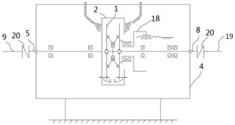
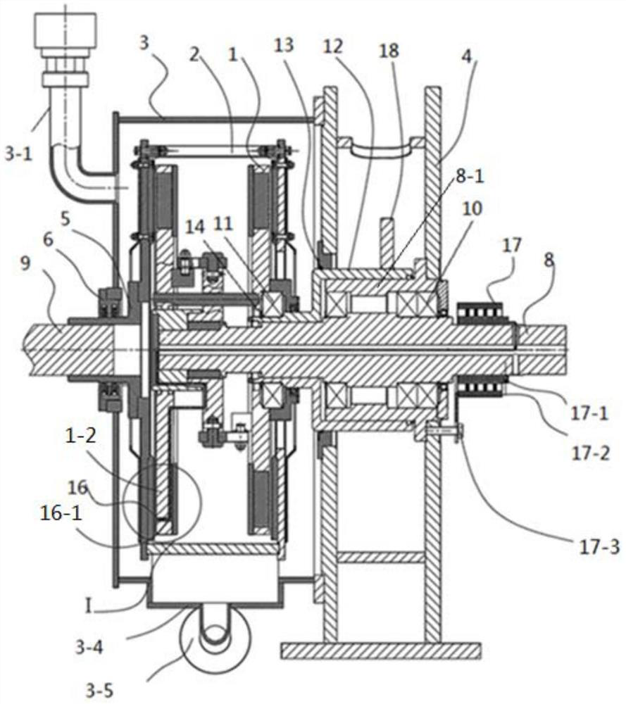
[0068] Specific implementation mode one: combine figure 2 with image 3 Describe this embodiment, the liquid-cooled speed-regulating magnetic clutch for ships described in this embodiment, the magnetic clutch includes a permanent disk assembly 1, a conductor disk assembly 2, a bracket 4, a conductor disk connecting flange 5, an air gap adjustment mechanism, Transmission shaft 8 and drive shaft 9,
[0069] One end of the transmission shaft 8 is connected to one end of the permanent disk assembly 1, and the other end of the transmission shaft 8 is connected to the load end,
[0070] The magnetic clutch also includes a casing 3, a floating seal 6, a cooling mechanism 7, a support bearing 10, an O-ring 13 and a sleeve 8-1,
[0071] The bracket 4 is composed of two support plates supporting each other,
[0072] The permanent disk assembly 1 comprises two permanent disks and a link mechanism, and the two permanent disks are connected by a link mechanism,
[0073] The conductor ...
specific Embodiment approach 2
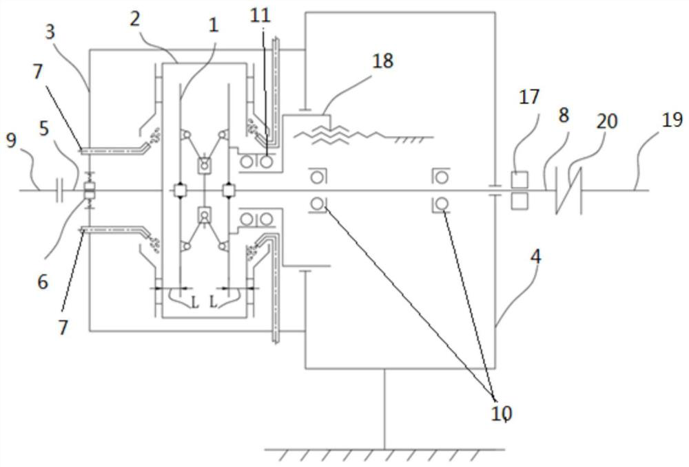
[0087] Specific implementation mode two: combination Figure 5 , Image 6 with Figure 7 , Figure 8 This embodiment is described. This embodiment is to further limit the liquid-cooled speed-regulating magnetic clutch for ships described in Embodiment 1. In this embodiment, two a cooling mechanism 7,
[0088] The two cooling mechanisms 7 on the outer wall of the casing 3 are arranged in a mirror image along the vertical middle plane where the axis of the transmission shaft 8 is located,
[0089] The two cooling mechanisms 7 on the inner wall of a support plate are arranged in a mirror image along the vertical mid-section plane where the axis of the transmission shaft 8 is located.
[0090] In this embodiment, if Figure 4 , Image 6 with Figure 7 As shown, two cooling mechanisms 7 are respectively arranged on the outer wall of the casing 3 and on the inner wall of a support plate. Image 6 In the figure, two cooling mechanisms 7 are arranged on the inner wall of a sup...
specific Embodiment approach 3
[0091] Specific implementation mode three: combination Figure 5 to Figure 8 Describe this embodiment. This embodiment is a one-step limitation of the liquid-cooled speed-regulating magnetic clutch for ships described in the second specific embodiment. In this embodiment, the magnetic clutch also includes two cooling channels, and two cooling flows The tracks are respectively arranged on the back irons 2-3 of the two conductor discs,
[0092] Each cooling channel includes a channel back plate 15-1 and an adjusting pad 15-2,
[0093] Fix the two flow channel back plates 15-1 on the back irons 2-3 of the two conductor plates respectively by bolts, and set between the back iron 2-3 of each conductor plate and each flow channel back plate 15-1 Adjustment pad 15-2, and the adjustment pad 15-2 is sleeved on the bolt, and the back plate of each flow channel is close to the injection port 7-1 of the cooling mechanism, and is provided with a ring-shaped liquid collection structure wit...
PUM
 Abstract
Description
Claims
Application Information
 - R&D
- Intellectual Property
- Life Sciences
- Materials
- Tech Scout
- Unparalleled Data Quality
- Higher Quality Content
- 60% Fewer Hallucinations
Browse by: Latest US Patents, China's latest patents, Technical Efficacy Thesaurus, Application Domain, Technology Topic, Popular Technical Reports.
© 2025 PatSnap. All rights reserved.Legal|Privacy policy|Modern Slavery Act Transparency Statement|Sitemap|About US| Contact US: help@patsnap.com