
Welding system for air conditioner refrigeration copper pipe and working method

A welding system, air-conditioning and refrigeration technology, applied in manufacturing tools, welding equipment, auxiliary welding equipment, etc., can solve the problems of inability to carry, unusable welding equipment, affecting use, etc., and achieve the effect of reducing legacy or loss.

Pending Publication Date: 2021-01-29
王学义
View PDF6 Cites 0 Cited by
  • Summary
  • Abstract
  • Description
  • Claims
  • Application Information

AI Technical Summary

Problems solved by technology

[0002] Air-conditioning copper pipe refers to the connecting copper pipe connecting the indoor unit and the outdoor unit of the air conditioner. The air-conditioning copper pipe has the characteristics of hard texture, not easy to corrode, high temperature resistance, high pressure resistance, etc., so it is deeply loved by people to achieve the purpose of easy operation. , but it still has disadvantages in actual use; for example, the refrigeration system in refrigeration and air conditioning generally uses non-ferrous metal materials such as copper and aluminum. In the process of manufacturing, installation and maintenance, the welding of pipelines is a key link. It not only affects It is beautiful, and more importantly, the problem that affects the normal operation of the system must be paid great attention to, but in the process of welding, stable control of the welding torch is required to better weld it;
[0003] The copper pipes of the air conditioner need to be fixed during welding. The welding needs to be fixed to prevent the two copper pipes from shifting during welding. However, the installation position of each air conditioner is different, resulting in that the two copper pipes are not at the same level after the welding is completed. The position affects the use, and the position of the air-conditioning copper pipe is not fixed. The existing welding equipment is too large and cannot be carried, so most of the welding equipment cannot be used.

Method used


Image

  • Welding system for air conditioner refrigeration copper pipe and working method
  • Welding system for air conditioner refrigeration copper pipe and working method
  • Welding system for air conditioner refrigeration copper pipe and working method

Examples


Embodiment Construction

[0031] In order to make the object, technical solution and advantages of the present invention clearer, the present invention will be further described in detail below in conjunction with the accompanying drawings and embodiments. It should be understood that the specific embodiments described here are only used to explain the present invention, not to limit the present invention.

[0032] The components of the embodiments of the invention generally described and shown in the figures herein may be arranged and designed in a variety of different configurations. Accordingly, the following detailed description of the embodiments of the invention provided in the accompanying drawings is not intended to limit the scope of the claimed invention, but merely represents selected embodiments of the invention.

[0033] Based on the embodiments of the present invention, all other embodiments obtained by persons of ordinary skill in the art without making creative efforts belong to the pro...


PUM


Abstract

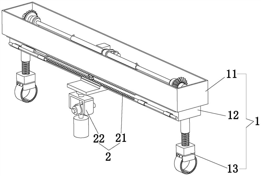
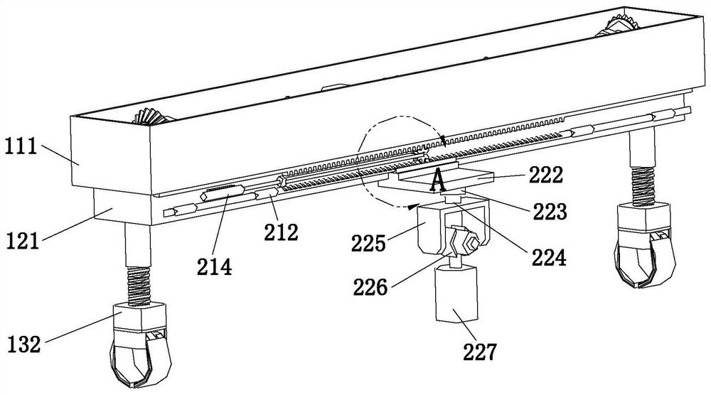
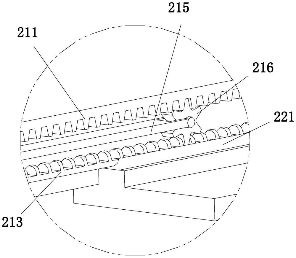
The invention discloses a welding system for an air conditioner refrigeration copper pipe and a working method, and relates to the technical field of air conditioner copper pipe machining.The weldingsystem comprises a fixing mechanism and a welding mechanism, the welding mechanism is arranged on the fixing mechanism, the fixing mechanism can be carried, and the fixing mechanism conducts fixing ormanual fixing according to the actual position. The welding system can conduct fixing at different positions, the problem that two copper pipes deviate during welding and are not located at the samehorizontal position after welding is completed can be solved, and compared with the welding technology in the prior art, the welding system can be carried, at some special positions, for example, theposition wherein equipment cannot be fixed, manual fixing can be conducted, and the problem that welding equipment in the prior art can work only after being fixed to a certain position is solved.

Description

technical field [0001] The invention relates to the technical field of air-conditioning copper pipe processing, in particular to a welding system and working method for air-conditioning refrigeration copper pipes. Background technique [0002] Air-conditioning copper pipe refers to the connecting copper pipe connecting the indoor unit and the outdoor unit of the air conditioner. The air-conditioning copper pipe has the characteristics of hard texture, not easy to corrode, high temperature resistance, high pressure resistance, etc., so it is deeply loved by people to achieve the purpose of easy operation. , but it still has disadvantages in actual use; for example, the refrigeration system in refrigeration and air conditioning generally uses non-ferrous metal materials such as copper and aluminum. In the process of manufacturing, installation and maintenance, the welding of pipelines is a key link. It not only affects It is beautiful, and more importantly, the problem that af...

Claims


Application Information

Patent Timeline
Patent Type & Authority Applications(China)
IPC IPC(8): B23K37/053B23K37/04B23K37/02B23K37/00B23K101/06B23K103/12
CPCB23K37/0533B23K37/0443B23K37/0252B23K37/00B23K2101/06B23K2103/12
Inventor 王学义
Owner 王学义
Learn More