
Robot external active gravity compensation system and simulation verification method

A technology of gravity compensation and simulation verification, applied in the field of robotics, can solve the problems of reducing joint response ability, not applicable to gravity compensation of large mass loads, and unable to simulate and verify the control effect of active gravity compensation system

Active Publication Date: 2021-01-29
GUANGDONG TOPSTAR TECH +1
View PDF6 Cites 1 Cited by
  • Summary
  • Abstract
  • Description
  • Claims
  • Application Information

AI Technical Summary

Problems solved by technology

In the counterweight balancing method commonly used in palletizing robots, the gravitational potential energy is exchanged between the structure of the manipulator and the counterweight, which improves the energy utilization efficiency of the system and reduces the joint torque demand, but this method increases the mass and inertia of the robot , reducing joint responsiveness
Juan Carlos Cambera uses a spring gravity compensation device to reduce the load on some joint axes of the robot, but this method has a poor compensation effect on the end joints and is not suitable for gravity compensation of large mass loads at the end of a six-axis robot
The external active gravity compensation device designed by Yang Zhang et al. achieves gravity compensation by adding additional auxiliary actuators, but due to the cooperative control problem, it can only realize the gravity compensation of the plane motion of the end load
[0005] System control with active gravity compensation needs to use dynamics simulation for effect verification, but the existing robot rigid body dynamics simulation lacks simulation support for passive joints and rope transmission, and cannot be applied to the control effect simulation verification of active gravity compensation system

Method used


Image

  • Robot external active gravity compensation system and simulation verification method
  • Robot external active gravity compensation system and simulation verification method
  • Robot external active gravity compensation system and simulation verification method

Examples


Embodiment Construction

[0036] The present invention will be further described below in conjunction with accompanying drawing:

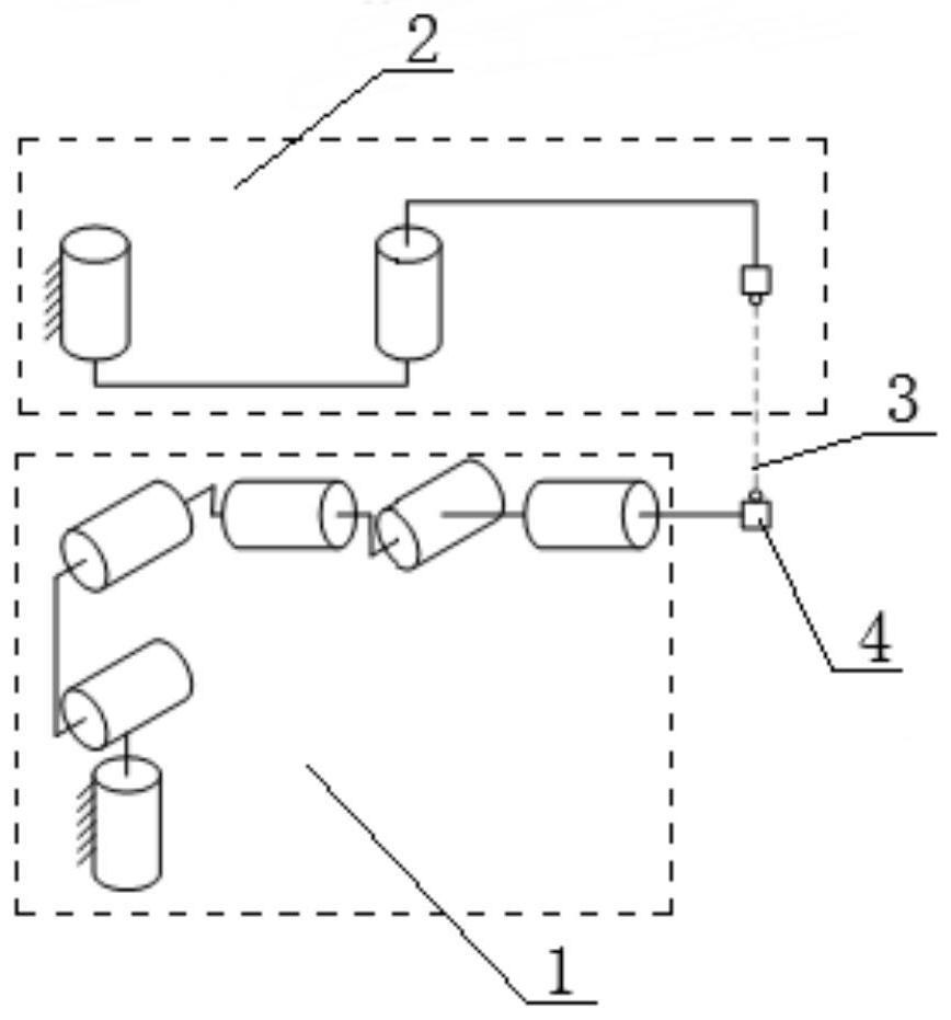
[0037] Such as figure 1 As shown: the present invention includes a gravity compensation device 2 and a gravity compensation rope 3, the force end of the gravity compensation device 2 is connected to one end of the gravity compensation rope 2, and the other end of the gravity compensation rope 2 is connected to the force end of the serial robot 1 , the force application end of the serial robot 1 is connected to the end load 4 at the same time.

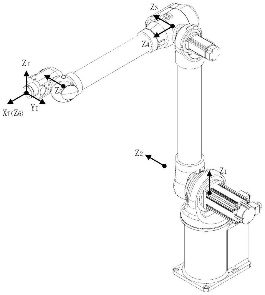
[0038] When using a small 6R robot to complete the assembly task of large-mass parts, in order to ensure the freedom of movement of the robot, an external gravity compensation system is used to directly compensate the gravity of the large-mass load at the end. The structure of robot and gravity compensation system is as follows: figure 1 shown. A variable-length belt-driven rope is used to connect the end of the robot to the end o...


PUM


Abstract

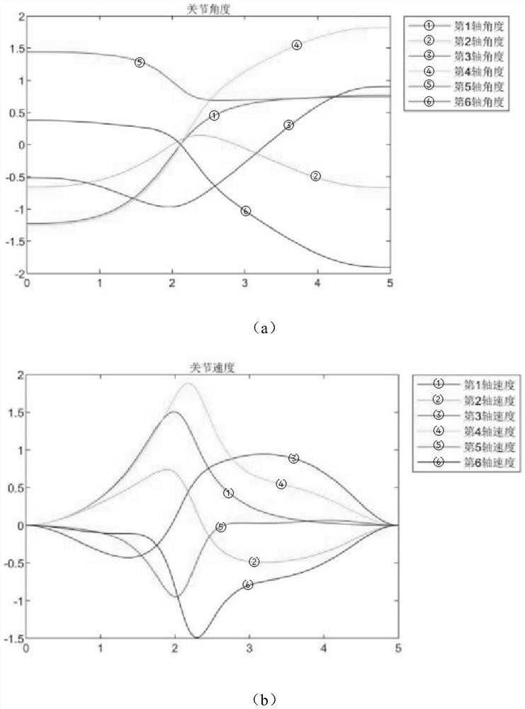
The invention discloses a robot external active gravity compensation system and a simulation verification method. The robot external active gravity compensation system comprises a gravity compensationdevice and a gravity compensation rope, the force application end of the gravity compensation device is connected with one end of the gravity compensation rope, the other end of the gravity compensation rope is connected with the force application end of a series robot, and the force application end of the series robot is connected with a tail end load at the same time. the small-load robot completes a large-load task. According to the structure of a robot and a gravity compensation device, a kinematics model is established based on a spinor theory, and a closed chain mechanism kinetic modelwith a passive joint is established by using a Newton-Euler's method. A linear moving track of a simulation experiment is designed, passive joint friction force and constant-torque gravity compensation are simulated in a dynamics simulation environment Coppeliasim, a small-load robot is used for completing the linear carrying action of large-mass parts in simulation, and the influence of differentgravity compensation torques on robot joint torque is researched.

Description

technical field [0001] The invention relates to the technical field of robots, in particular to a robot external active gravity compensation system and a simulation verification method. Background technique [0002] The manufacturing industry and the construction industry often need to control large-mass components to complete stacking or assembly operations, such as wall-laying operations in residential buildings, stacking and assembly of large-mass parts and other large-load mobile operations. Most of the repetitive operations can be replaced by six-degree-of-freedom robots artificial. Using a 6DOF robot can improve repeatability, precision and speed compared to manual operations. However, there are some defects in the existing robots. For example, the load-to-weight ratio of traditional six-axis industrial robots is generally less than 0.15. Large-load operations require the use of expensive heavy-load robots, and because of their heavy weight, they cannot be moved, so t...

Claims


Application Information

Patent Timeline
Patent Type & Authority Applications(China)
IPC IPC(8): B25J9/16B25J19/00
CPCB25J9/1638B25J19/0008
Inventor 宋宝刘永兴唐小琦周向东肖千红钟靖龙郭艺璇徐必业王志成
Owner GUANGDONG TOPSTAR TECH
Learn More