Eureka AIR delivers breakthrough ideas for toughest innovation challenges, trusted by R&D personnel around the world.

Leg structure with low inertia and high load and legged robot using it

A high-volume technology for legs, applied in the field of robotics, can solve the problems of increasing the equivalent moment of inertia of the previous joints, reducing the dynamic response capability of the leg structure, and the weight of the joint support structure, so as to reduce the equivalent moment of inertia , reduce structural complexity and structural weight, and improve the effect of load capacity

Active Publication Date: 2022-01-07
HUAZHONG UNIV OF SCI & TECH +1
View PDF13 Cites 0 Cited by
  • Summary
  • Abstract
  • Description
  • Claims
  • Application Information

AI Technical Summary

Problems solved by technology

[0005] (1) The tandem leg structure with hip-knee coaxiality mainly relies on joint shaft transmission, the transmission relationship is coupled with each other, and the load is amplified layer by layer, resulting in heavy weight of the joint support structure, weakening the stiffness of the joint, and reducing the bearing capacity;
[0006] (2) Due to the existence of the series relationship of the joints, the joints of the latter stage as a whole act as the load of the joints of the previous stage, thus increasing the equivalent moment of inertia of the joints of the previous stage and reducing the dynamic response capability of the leg structure
[0007] The existence of these problems leads to the limitation of the load capacity of the robot

Method used


Image

  • Leg structure with low inertia and high load and legged robot using it
  • Leg structure with low inertia and high load and legged robot using it
  • Leg structure with low inertia and high load and legged robot using it

Examples


Embodiment Construction

[0034] In order to make the object, technical solution and advantages of the present invention clearer, the present invention will be further described in detail below in conjunction with the accompanying drawings and embodiments. It should be understood that the specific embodiments described here are only used to explain the present invention, not to limit the present invention. In addition, the technical features involved in the various embodiments of the present invention described below can be combined with each other as long as they do not constitute a conflict with each other.

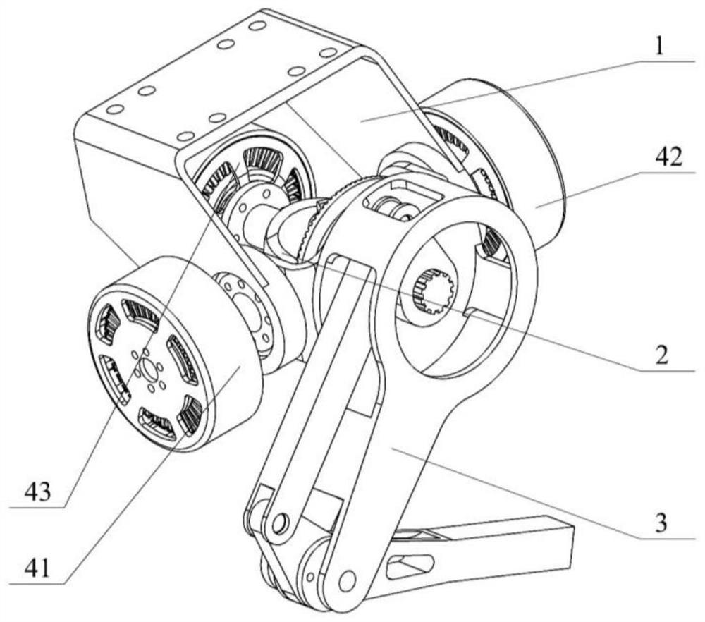
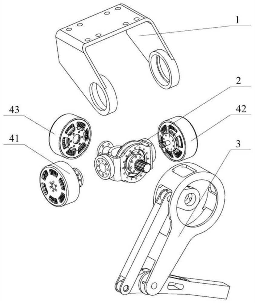
[0035] The body of the legged robot is similar to the upper body of a human or the body of a quadruped animal. The body is a frame structure, and the power battery, motor driver, control computer, and environmental perception sensors of the robot are placed in the frame. The mechanical interface connected by the external connector 1, the multiple legs jointly support the frame of the robot body,...


PUM


Abstract

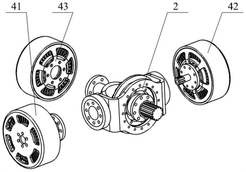
The invention belongs to the technical field related to robots, and discloses a leg structure with low inertia and high load and a footed robot using the same. The leg structure includes a crotch connector, a pelvis assembly, a knee joint motor, a hip joint motor, a side swing joint motor and a leg link, wherein: the crotch connector is connected with the stators of the above three motors at the same time, and the three The rotors of the motors are respectively connected to the pelvis assembly, the motor of the side swing joint is coaxially opposite to the motor of the hip joint, the axis of the motor of the knee joint is perpendicular to the axis of these two motors, the motor of the hip joint drives the thigh connecting rod to rotate, and the motor of the knee joint drives the connecting rod of the calf The rod rotates, and the side swing joint motor drives the leg link to swing sideways, so as to realize the outward swing and retraction of the robot's legs and the flexion and extension of the thigh and calf. Through the present invention, the three joint motors are connected to the fuselage in parallel, and the pelvis assembly performs power splitting, thereby reducing the inertia of the legs, enhancing the rigidity of the legs, and improving the bearing and dynamic response capabilities.

Description

technical field [0001] The invention belongs to the technical field related to robots, and more specifically relates to a leg structure with low inertia and high load and a legged robot using the same. Background technique [0002] Legged robots generally use a multi-link leg configuration to achieve walking and jumping movements, so the overall performance of the robot largely depends on the mobility of the robot legs. High-performance legged robots require legs with high load-carrying capacity, light weight, small inertia, and high dynamic response. However, due to the existence of scale effects, these target requirements often conflict, which poses challenges to the structural design of the legs. How to adopt delicate It has become a hot and difficult point in the research and development of high-performance legged robots to resolve the conflict of design goals by rationally configuring the structural parameters. [0003] At present, relevant institutions and R&D personn...

Claims


Application Information

Patent Timeline
Patent Type & Authority Patents(China)
IPC IPC(8): B62D57/032
CPCB62D57/032
Inventor 罗欣贾文川王泽宇李琦刘军军马书根
Owner HUAZHONG UNIV OF SCI & TECH
Why Eureka
Eureka Blog
Learn More