Special cutting tool for transformer oil-resistant sealing ring

An oil-resistant sealing ring and cutting tool technology, which is applied in metal processing and other directions, can solve the problems of inappropriate size of the spare sealing ring, insufficient sealing accuracy, and cumbersome cutting instruments, so as to achieve low manufacturing and use costs, and improve cutting accuracy and efficiency. , the effect of reducing labor intensity

Pending Publication Date: 2021-01-29
KUYTUN POWER SUPPLYING CO STATE GRID XINJIANG ELECTRIC POWER CO
View PDF0 Cites 0 Cited by
  • Summary
  • Abstract
  • Description
  • Claims
  • Application Information

AI Technical Summary

Problems solved by technology

[0003] At present, due to the variety of specifications and sizes of the flanges at the transformer connection, there are often situations where there is no spare seal ring or the size of the spare seal ring is not suitable. Therefore, maintenance personnel are required to carry rubber sheets and cutting tools for on-site cutting. The function of the cutting tool is not perfect, and maintenance personnel need to use a meter ruler to measure the inner diameter and outer diameter of the connecting flange sealing ring; ...

Method used


Image

  • Special cutting tool for transformer oil-resistant sealing ring
  • Special cutting tool for transformer oil-resistant sealing ring
  • Special cutting tool for transformer oil-resistant sealing ring

Examples


Embodiment 1

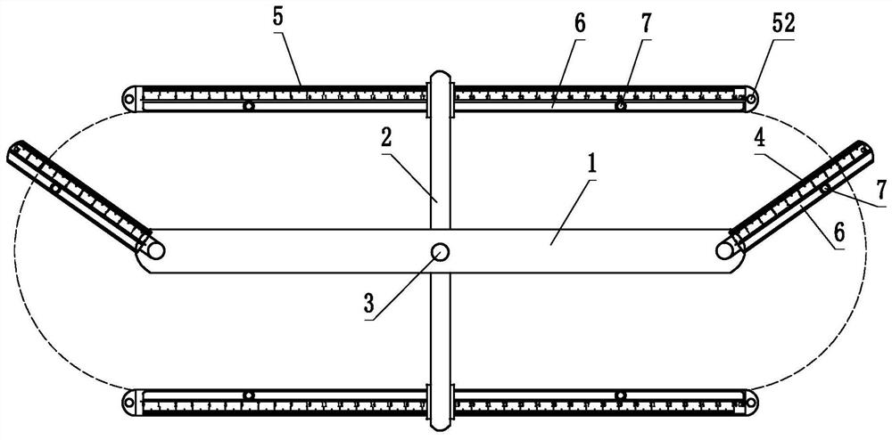
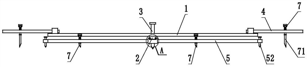
[0030] This embodiment provides a special cutting tool for transformer oil-resistant sealing rings. The tool includes a skeleton, and the skeleton includes a transverse skeleton 1 and a longitudinal skeleton 2 crossed and fixed with the transverse skeleton 1. In this embodiment, the transverse skeleton is preferred. The intersection point of 1 and longitudinal frame 2 is fixed by bolts or pins, and the angle between horizontal frame 1 and longitudinal frame 2 can be adjusted by adjusting the tightness of bolts or pins. And / or the central point of the transverse frame 1 is provided with a positioning pin A3, when the cross fixing point is provided with a positioning pin A3, the positioning pin A3 can be a screw or a pin for fixing the transverse frame 1 and the longitudinal frame 2, see Figure 1-3 ; The two ends of the transverse framework 1 are respectively hinged with a measuring arm A4, and the measuring arm A4 can be rotated relative to the transverse framework 1 with the h...

Embodiment 2

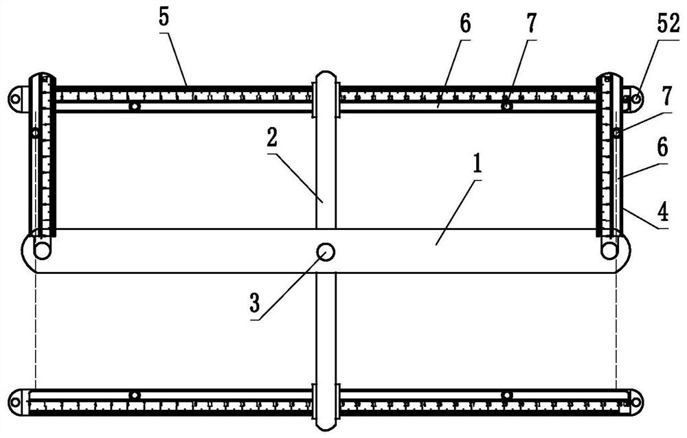
[0036] Compared with Embodiment 1, the difference of this embodiment is that two groups of longitudinal skeletons 2 parallel to each other are arranged on the transverse skeleton 1, and the two groups of longitudinal skeletons 2 parallel to each other and the transverse skeleton 1 are connected by pins or spirals at the intersection points. fixed, see Figure 9-10 , the cutting tool with this structure can make the movement of the measuring arm B5 more stable and synchronous.


PUM


Abstract

The invention discloses a special cutting tool for a transformer oil-resistant sealing ring. The special cutting tool comprises a framework, the framework comprises a transverse framework and at leastone longitudinal framework fixed with the transverse framework in a crossed manner; a positioning needle A is arranged at a crossed fixing point of the transverse framework and the longitudinal framework and/or the central point of the transverse framework; measuring arms A are hinged to the two ends of the transverse framework respectively and can rotate relative to the transverse framework witha hinge point as the circle center; the two ends of the longitudinal framework are each provided with at least one group of measuring arms B, and the measuring arms B can reciprocate in the length direction of the longitudinal framework; the measuring arms A and the measuring arms B are provided with scales and rails in the length direction of the measuring arms A and the measuring arms B respectively; and the rails penetrate through the measuring arms, at least one group of cutting knife assemblies are arranged in the rails, each cutting knife assembly comprises a cutting knife and a lockingpiece, and the locking pieces can fix the cutting knives to the rails. The cutting efficiency and precision of the transformer oil-resistant sealing ring can be improved through the cutting tool.

Description

technical field [0001] The invention specifically relates to a special cutting tool for an oil-resistant sealing ring of a transformer. Background technique [0002] As a kind of seal, the transformer oil-resistant sealing ring plays a key role in the operation of the transformer. If the sealing ring is aging and is not replaced in time, it will cause oil leakage at the transformer connection. Therefore, maintenance personnel need to carry out regular inspections on the transformer sealing ring. Check and replace. [0003] At present, due to the variety of specifications and sizes of the flanges at the transformer connection, there are often situations where there is no spare seal ring or the size of the spare seal ring is not suitable. Therefore, maintenance personnel are required to carry rubber sheets and cutting tools for on-site cutting. The function of the cutting tool is not perfect, and maintenance personnel need to use a meter ruler to measure the inner diameter an...

Claims


Application Information

Patent Timeline
IPC IPC(8): B26D1/28B26D7/28B26D7/26
CPCB26D1/285B26D7/2614B26D7/28
Inventor 孙军海顾世峰李保华童波赵一鑫文强叶尔森·赛里克邵军张博
Owner KUYTUN POWER SUPPLYING CO STATE GRID XINJIANG ELECTRIC POWER CO
Why Eureka
Try Eureka