A solid wood processing side staggered precision cutting wood art base cutting device
A cutting device and precise technology, applied in the field of solid wood processing side staggered precision cutting wood art base cutting device, can solve the problems of precise positioning of four-corner wooden blocks, no protective operators, low work efficiency, etc., to ensure accuracy and shape Beautiful, time-saving effect of cutting corners
- Summary
- Abstract
- Description
- Claims
- Application Information
AI Technical Summary
Problems solved by technology
Method used
Image
Examples
Embodiment 1
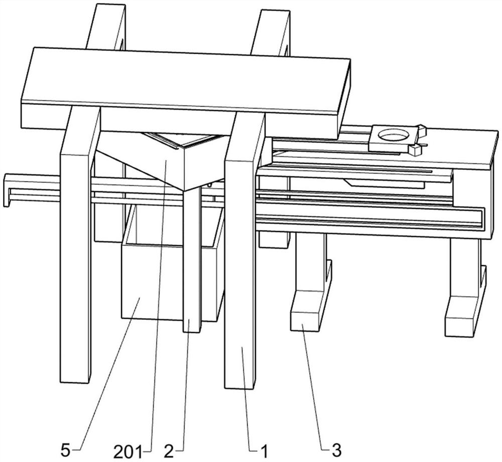
[0031] see Figure 1-9 , a solid wood processing side staggered precision cutting wood art base cutting device, including a first support frame 1, a cutting mechanism, a support mechanism and a material box 5, four first support frames 1 are arranged in an array, the cutting mechanism and the second A support frame 1 is fixedly connected, the support mechanism is located below the cutting mechanism, the support mechanism cooperates with the cutting mechanism, and the material box 5 is placed vertically below the support mechanism.
[0032] During the corner cutting process of the four-corner wooden blocks, the worker puts the four-corner wooden blocks that need to be cut into the transmission mechanism, and the transmission mechanism sends the wooden blocks to the support mechanism. After the support mechanism accurately positions the four-corner wooden blocks, the cutting mechanism is divided into two Carry out the corner cutting process on the four-corner wood block. After t...
Embodiment 2
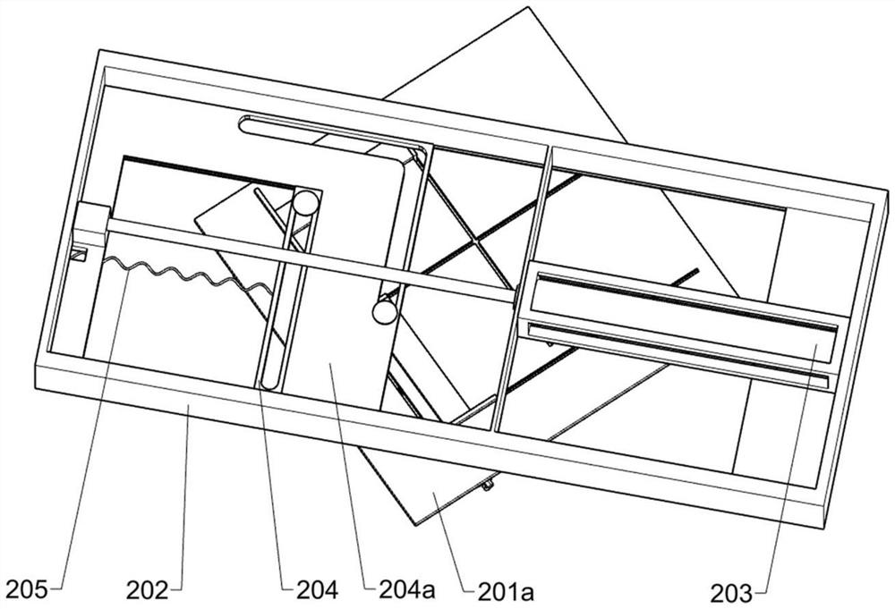
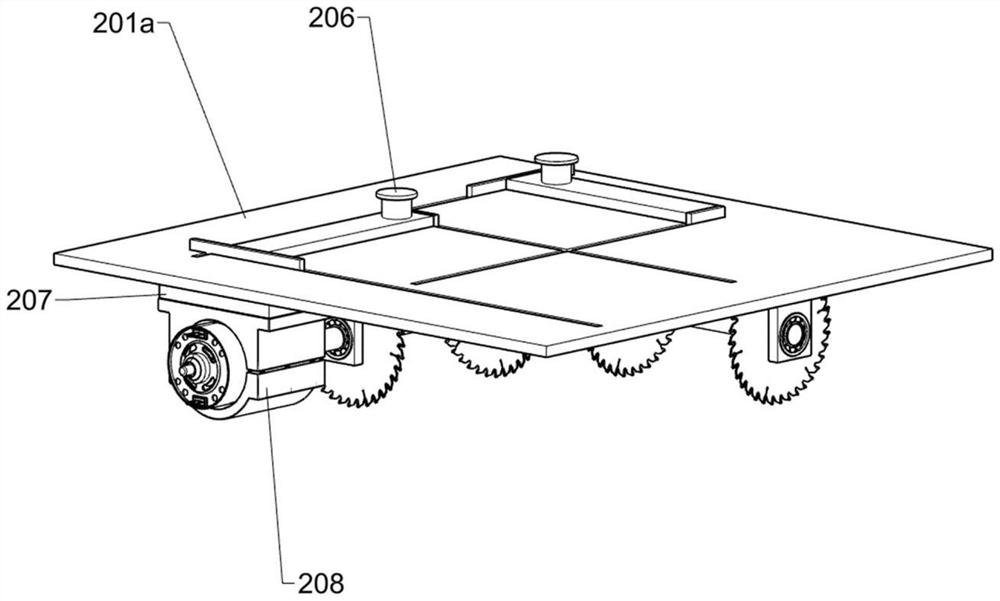
[0034] On the basis of Example 1, please refer to Figure 2-9, the cutting mechanism includes a first support plate 2, a first support frame 201, a second fixed plate 201a, a first slide frame 202, a first air cylinder 203, a second slide frame 204, a first tension spring 205, a first slide column 206, skateboard, motor 208, shaft rod 209 and helical gear 210, the two first support plates 2 are placed between the two four first support frames 1, and the first support frame 201 is fixedly installed on the two first support frames 1. The upper end of the support plate 2, the second fixed plate 201a is fixedly installed on the top of the first support frame 201, the second fixed plate 201a is provided with L-shaped chute and cross chute, the first slide frame 202 is fixedly installed on the four first In the middle of the support frame 1, the first cylinder 203 is fixedly installed on the inner right side of the first sliding frame 202, and the first sliding plate 204a is slidabl...
Embodiment 3
[0039] On the basis of Example 1, please refer to Figure 5 with Figure 8 , the slanting block provided on the second support frame 3 is divided into two types of inclined sides, the right side is set to incline, and the left side is set to incline downward, which facilitates the movement of the fourth support frame 303 without interference.
[0040] The left side of the slanting block in the middle part of the second support frame 3 is set to be inclined downward, which facilitates when the third support frame 301 and the fourth support frame 303 move to the right, and the fourth support frame 303 can move down with the inclined block, so that The upper end of the fourth bracing frame 303 is positioned at the below of the second bracing frame 3 upper sides, prevents the fourth bracing frame 303 from being unable to realize the transmission four-corner block, and the right side of the inclined block is set to be inclined inwardly, has facilitated the fourth bracing frame 303 ...
PUM
 Abstract
Description
Claims
Application Information
 - R&D
- Intellectual Property
- Life Sciences
- Materials
- Tech Scout
- Unparalleled Data Quality
- Higher Quality Content
- 60% Fewer Hallucinations
Browse by: Latest US Patents, China's latest patents, Technical Efficacy Thesaurus, Application Domain, Technology Topic, Popular Technical Reports.
© 2025 PatSnap. All rights reserved.Legal|Privacy policy|Modern Slavery Act Transparency Statement|Sitemap|About US| Contact US: help@patsnap.com


