
Automatic transferring device

A transfer device and automatic technology, applied in the direction of lifting device, transportation and packaging, load hanging components, etc., can solve the problems of limited adaptability, loss of effective stroke, difficult to apply reasonably, etc., to achieve stable movement and small limitations , the effect of strong bearing capacity

Pending Publication Date: 2021-01-29
AEROSUN CORP
View PDF0 Cites 1 Cited by
  • Summary
  • Abstract
  • Description
  • Claims
  • Application Information

AI Technical Summary

Problems solved by technology

The existing problems are firstly that the adaptability is limited, the multi-dimensional manipulator with spatial motion mechanism is expensive and the stability is not good; secondly, since the linear guide rail cannot be stretched and folded, it will lose a lot of effective travel in the case of limited vertical space, and it is difficult to Reasonable application; In addition, in order to meet the needs of grasping various forms of goods, the manipulator often uses vacuum suction cups as the actuator, which cannot avoid the falling of the goods caused by factors such as the outer packaging of the goods being sucked.

Method used


Image

  • Automatic transferring device
  • Automatic transferring device
  • Automatic transferring device

Examples


Embodiment Construction

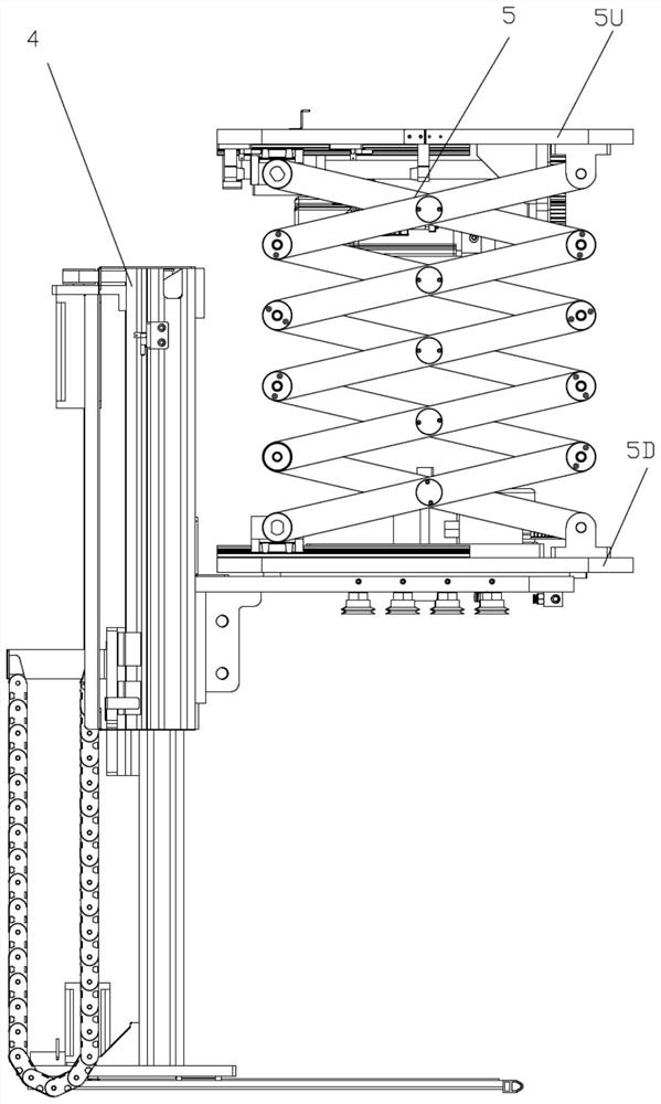
[0028] The basic structure of this automatic transfer device is as follows: figure 1 As shown, it includes a scissors mechanism 5 installed between the upper mounting plate and the lower mounting plate, and a bottom pallet elevating mechanism 4 connected with the scissors mechanism 5 through the lower mounting plate.

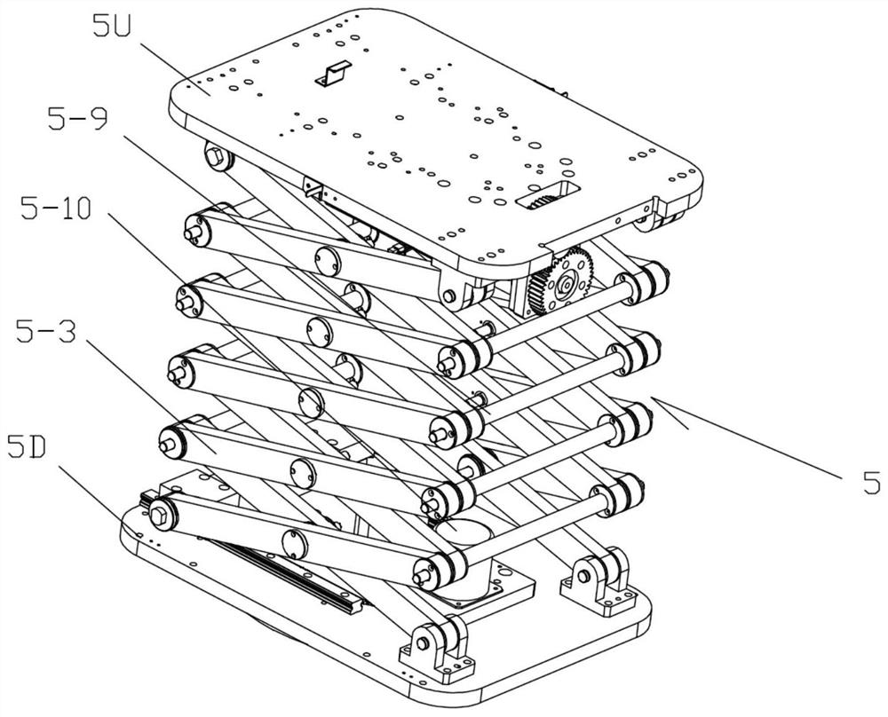
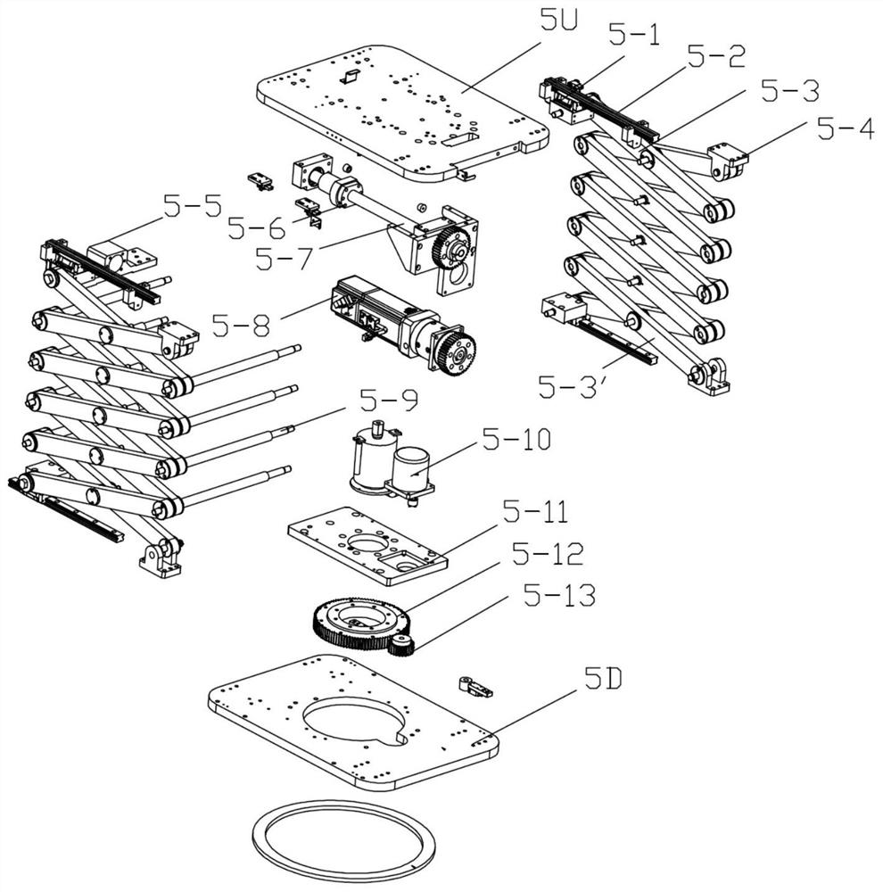
[0029] The concrete structure of scissor mechanism 5 is as figure 2 , image 3 As shown, there are left and right paired X-shaped connecting rods 5-3 each of five groups of which are hinged at the midpoint, wherein the right end of the uppermost X-shaped connecting rod is hinged on the upper hinge fixed on the lower surface of the upper mounting plate 5U. Support block 5-4, left end are hinged on upper slide block 5-1, and this upper slide block 5-1 and the upper slide rail 5-2 that is fixed on the upper mounting plate 5U lower surface constitute mobile pairs. The right end of the bottom X-shaped connecting rod 5-3' is hinged on the lower hinge support fixed ...


PUM


Abstract

The invention relates to an automatic transferring device, and belongs to the technical field of goods transferring and conveying equipment. The automatic transferring device comprises a shear fork mechanism and a bottom supporting plate lifting mechanism, wherein the shear fork mechanism is mounted between an upper mounting plate and a lower mounting plate. The shear fork mechanism is composed ofa set of X-shaped connecting rods with the middle points hinged. The bottom supporting plate lifting mechanism comprises a rotating bottom plate with a suction cup on the lower surface, wherein one side of the rotating bottom plate is fixedly connected with a vertical column, and the vertical column and a lifting column with a bottom supporting plate installed at the lower end form a sliding pair. The lower mounting plate and the rotating bottom plate form a vertically constrained rotating pair. Due to the fact that the automatic transferring device is formed by completely overlapping and combining the planar motion mechanisms, the bearing capacity is high, and motion is stable; the stroke of the shear fork mechanism and the stroke of the bottom supporting plate lifting mechanism have vertical overlapping areas, so that space is fully utilized, and limitation is small; and in addition, by means of the bottom supporting plate for bearing and sucking goods, safety and reliability of transferring are ensured.

Description

technical field [0001] The invention relates to a transfer device, in particular to an automatic transfer device, which belongs to the technical field of cargo transfer and conveying equipment. Background technique [0002] As far as the applicant knows, in order to realize the transfer of stacked goods on one side to the stacked stack on the other side, the existing truss-type transplanting equipment generally adopts the design scheme of linear guide rail supporting the manipulator in order to improve efficiency. The existing problems are firstly that the adaptability is limited, the multi-dimensional manipulator with spatial motion mechanism is expensive and the stability is not good; secondly, since the linear guide rail cannot be stretched and folded, it will lose a lot of effective travel in the case of limited vertical space, and it is difficult to Reasonable application; In addition, in order to meet the needs of grasping various forms of goods, the manipulator often ...

Claims


Application Information

Patent Timeline
IPC IPC(8): B66F7/06B66F7/28B66C1/02B65G47/74
CPCB65G47/74B66C1/025B66F7/0608B66F7/0666B66F7/28
Inventor 魏朕刘进江国海啸王强何磊
Owner AEROSUN CORP
Learn More