
Cylindrical self-circulation denitrification integrated sewage treatment equipment based on aerobic granular sludge

A technology for aerobic granular sludge and sewage treatment equipment, which is applied in water/sludge/sewage treatment, biological water/sewage treatment, aerobic and anaerobic process treatment, etc. Problems such as dead corners of equipment and sludge accumulation can be avoided to prevent sludge from turning black and floating up, and prevent sludge from accumulating

Pending Publication Date: 2021-01-29
SHANDONG ZIER ENVIRONMENTAL TECH CO LTD
View PDF0 Cites 3 Cited by
  • Summary
  • Abstract
  • Description
  • Claims
  • Application Information

AI Technical Summary

Problems solved by technology

[0003] At present, comprehensive research on the aerobic granular sludge process has been carried out at home and abroad, but there are still problems in the cultivation and use of aerobic granular sludge. Aerobic granular sludge is easy to disintegrate during repeated operations, and most equipment The existence of dead corners leads to sludge accumulation, and the sludge turns black and floats up after a long time, which increases the difficulty of cultivating aerobic granular sludge and treating sewage

Method used


Image

  • Cylindrical self-circulation denitrification integrated sewage treatment equipment based on aerobic granular sludge
  • Cylindrical self-circulation denitrification integrated sewage treatment equipment based on aerobic granular sludge
  • Cylindrical self-circulation denitrification integrated sewage treatment equipment based on aerobic granular sludge

Examples


Embodiment Construction

[0028] The present invention will be further described below in conjunction with the accompanying drawings and embodiments.

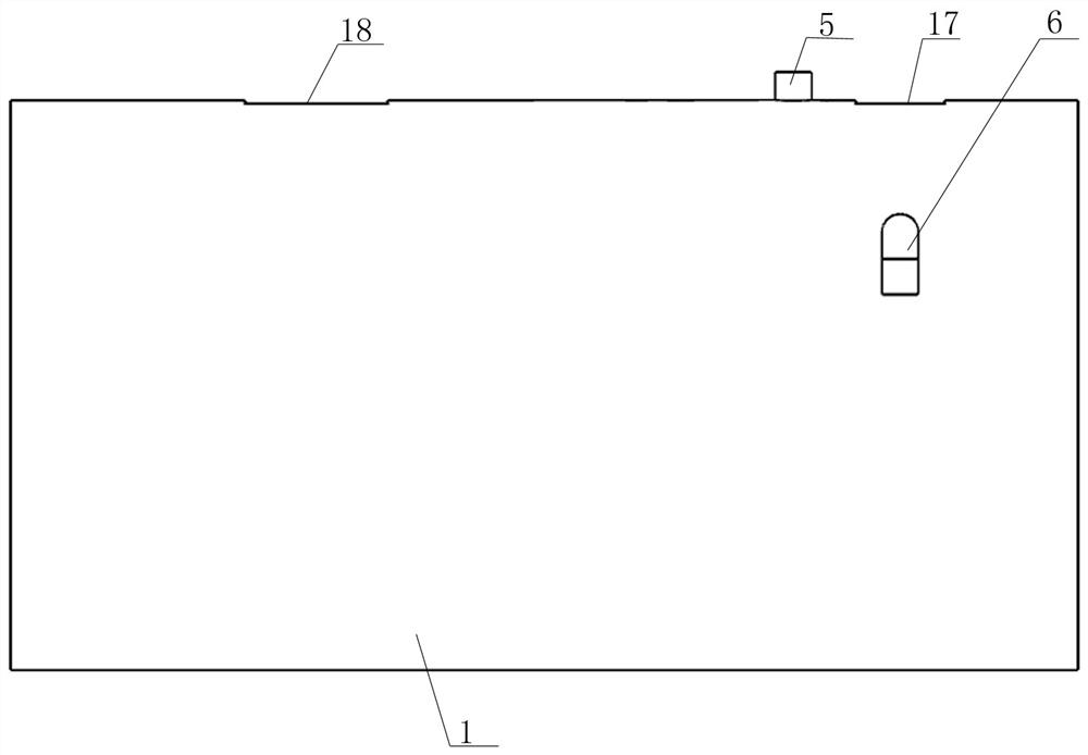
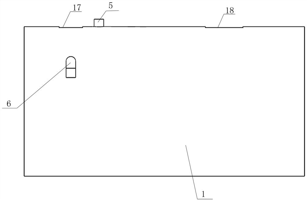
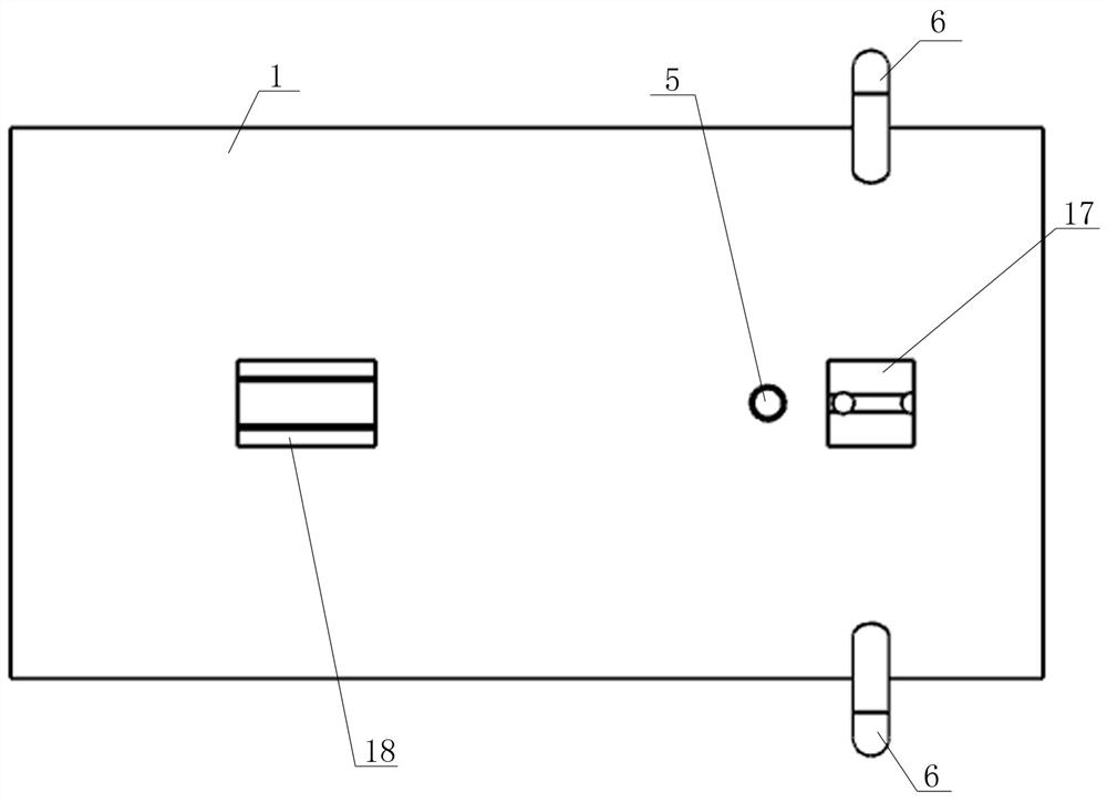
[0029] Such as Figure 1 to Figure 5 As shown, the front view, rear view, top view, perspective view and perspective view of the cylindrical self-circulating denitrification integrated sewage treatment equipment of the present invention are provided respectively, Figure 7 with Figure 8 A cross-sectional view is given, Image 6 A schematic diagram of the structure after the shell is removed is given. The integrated sewage treatment equipment shown is composed of a cylinder body 1, a partition plate 2, an aeration tank 3, an upflow reaction tank 4, an inlet pipe 5, an outlet pipe 6, and an aeration tank. Air unit 7, return pipe 8, water distribution pipe 9, water outlet weir 10, water collection tank 11, aeration tank inlet pipe 12, upper baffle 14 and lower baffle 15, the cylinder 1 is placed horizontally and horizontally, and its interior is a cylin...


PUM


Abstract

The invention relates to a cylindrical self-circulation denitrification integrated sewage treatment equipment based on aerobic granular sludge, which comprises a cylinder, a water inlet pipe, a wateroutlet pipe, an aeration tank and an up-flow reaction tank, an aeration unit and a water distribution pipe are arranged in the aeration tank and the up-flow reaction tank respectively, the aeration tank is communicated with the up-flow reaction tank through a return pipe, an effluent weir and a water collecting tank are arranged at the upper part of the up-flow reaction tank; the effluent weir iscommunicated with the water collecting tank; the water collecting tank is communicated with the aeration tank through an aeration tank water inlet pipe; an upper baffle plate and a lower baffle plateare arranged on two sides of the aeration tank, a settling zone is formed between the baffle plates and the cylinder, and the water outlet pipe is communicated with the settling zone. According to thesewage treatment equipment disclosed by the invention, sludge accumulation is avoided by utilizing the characteristic that the inner cavity of the cylinder has no dead angle; the sewage circularly flows between the up-flow reaction tanks of the aeration tank through aeration, external power is not needed, and the energy consumption is reduced; due to the action of the upper baffle plate and the lower baffle plate, sewage is naturally settled in the settling zone, so that the concentration of suspended particles in effluent is extremely low, and the discharge requirement is met.

Description

technical field [0001] The present invention relates to a kind of sewage treatment equipment, more specifically, especially to a self-circulation of sewage formed by the pressure difference and liquid level difference between the upflow reaction tank and the aeration tank, in the aeration tank Dissolved oxygen provided by separate aeration circulates into the entire reaction tank, and a single sedimentation zone is set up in the aeration tank through a baffle to further treat the sewage in the reaction tank, and to meet higher water quality requirements based on aerobic granular sludge. Circular denitrification integrated sewage treatment equipment. Background technique [0002] The environment contains a large amount of high-concentration organic wastewater. High-concentration organic wastewater not only makes the water lose its use value, but also seriously affects the normal life of people near the water. At the same time, it accumulates and stores in the water and soil a...

Claims


Application Information

Patent Timeline
IPC IPC(8): C02F3/30C02F7/00C02F101/30
CPCC02F3/302C02F7/00C02F2101/30Y02W10/10
Inventor 戚伟康李博施棋刘丽芳
Owner SHANDONG ZIER ENVIRONMENTAL TECH CO LTD
Learn More