Micro valve used for micro channel flowing control and control method thereof

A kind of technology of flow control, control method

Active Publication Date: 2021-01-29
南京智升源建筑环境科技有限公司 +1
View PDF4 Cites 0 Cited by
  • Summary
  • Abstract
  • Description
  • Claims
  • Application Information

AI Technical Summary

Problems solved by technology

(4) Packaging is a difficult point in MEMS applications, and it is a big challenge in microfluidic systems
But so far, each micro valve still has its own shortcomings, and there is still enough room for development to improve performance and reduce costs to achieve product commercialization
In addition, based on the integration of microfluidic mechanics, chemistry, biology, microfluidic control and other theories, the optimal design and control theory of microvalve is not perfect, and the ideal design method from chip performance, structural design to manufacturing process cannot be realized.

Method used


Image

  • Micro valve used for micro channel flowing control and control method thereof
  • Micro valve used for micro channel flowing control and control method thereof
  • Micro valve used for micro channel flowing control and control method thereof

Examples


Embodiment 1

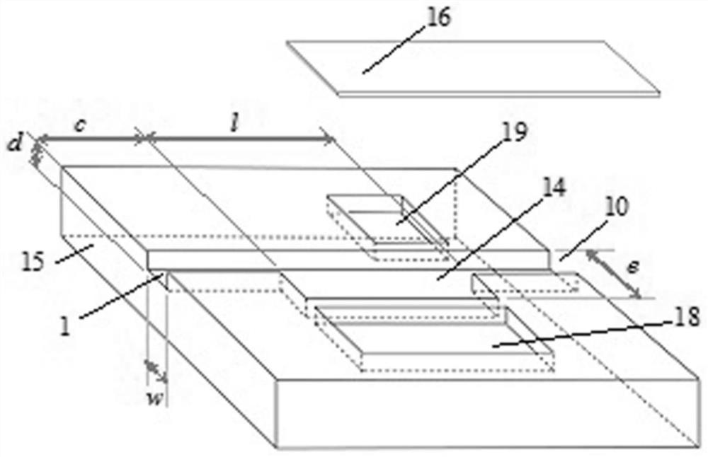
[0030] combine Figure 1, a micro-valve for micro-channel flow control, comprising a substrate 15, a micro-channel 14 is arranged in the middle of the substrate 15, an upstream micro-channel 1 is provided at one end of the micro-channel 14, a downstream micro-channel 10 is provided at the other end, and a downstream micro-channel 10 is provided at the other end of the micro-channel 14. Channel 1, microchannel 14 and downstream microchannel 10 form a series connection.

[0031] The width of the upstream microchannel 1 is equal to the width of the downstream microchannel 10, and is w, the depth of the upstream microchannel 1 is equal to the depth of the downstream microchannel 10, and is d, and the width of the microchannel 14 is that of the upstream microchannel 1 Twice the width, the width e is taken as 2w, the depth is equal to the depth of the downstream microchannel 10, which is d, and the length is l.

[0032] The inner surface of the micro-channel 14 is coated with a lef...

Embodiment 2

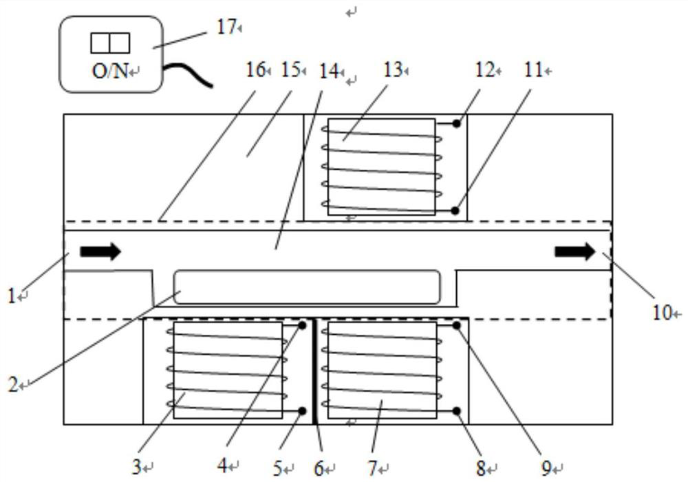
[0042] combine Figure 2-Figure 5 , a kind of control method for the microvalve of microchannel flow control, it is characterized in that, controller 17 controls the unlatching of first miniature magnetic field generator 3, the second miniature magnetic field generator 7 and the 3rd miniature magnetic field generator 13, Form vertical or horizontal magnetic field lines; change the pressure difference between the upstream microchannel 1 and the downstream microchannel 10 to change the magnetic intensity.

[0043] When the valve is opened, the first miniature magnetic field generator 3 and the second miniature magnetic field generator 7 are opened by the controller 17, and the third miniature magnetic field generator 13 is closed, so that the magnetorheological fluid 2 is attracted by the lines of magnetic force and fixed on the miniature magnetic field generator. The channel 14 is close to the side of the slot 18 where the first micro-magnetic field generator is placed, and the...

Embodiment 3

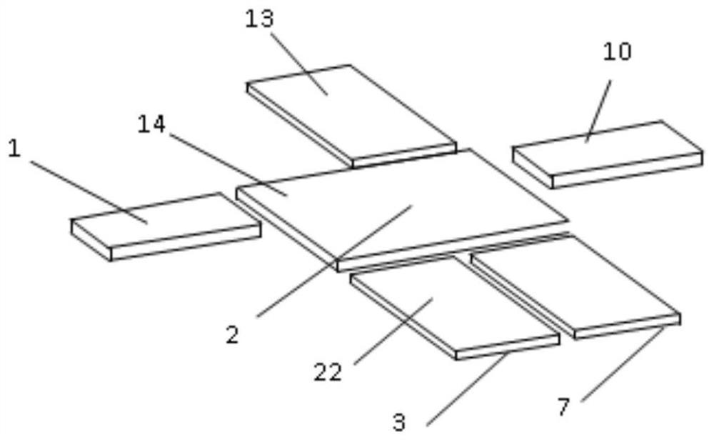
[0048] The control methods of the three miniature magnetic field generators on the magnetorheological fluid 2 include:

[0049] 1. When the valve is opened, the magnetorheological fluid 2 is piled up on the side of the micro-channel 14 close to the first micro-magnetic field generator placement groove 18, and the fluid medium flowing through the upstream microchannel 1 and the downstream microchannel 10 has a positive impact on the magnetorheological fluid. 2 acts on the friction force along the flow direction. At this time, the resultant force of the magnetic field force of the first micro-magnetic field generator 3 and the second micro-magnetic field generator 7 acting on the magnetorheological fluid 2 and the surface tension of the micro-channel 14 and the fluid and the frictional force between the magnetorheological fluid 2 is balanced, and the magnetorheological fluid 2 is in a static and stable state;

[0050] 2. When the valve is closed, the magnetorheological fluid 2 i...


PUM


Abstract

The invention discloses a micro valve used for micro channel flowing control. The micro valve comprises a base plate, and is characterized in that a micro slot path is arranged on the middle part of the base plate, wherein an upstream micro channel is arranged at one end of the micro slot path, a downstream micro channel is arranged at the other end of the micro slot path; magnetorheological fluidis arranged in the micro slot path; a cover plate is arranged above the upstream micro channel, the micro slot path and the downstream micro channel; a first micro magnetic field generator mounting slot is formed in one side of the micro slot path; a second micro magnetic field generator mounting slot is formed in the other side of the micro slot path; a first micro magnetic field generator and asecond micro magnetic field generator are horizontally arranged in the first micro magnetic field generator mounting slot; a first micro magnetic field generator positive electrode terminal is arranged at the upper end of the first micro magnetic field generator; a first micro magnetic field generator negative electrode terminal is arranged at the lower end of the first micro magnetic field generator; a second micro magnetic field generator positive electrode terminal is arranged at the upper end of the second micro magnetic field generator; and a second micro magnetic field generator negative electrode terminal is arranged at the lower end of the second micro magnetic field generator.

Description

technical field [0001] The invention relates to the field of fluid measurement and control, in particular to a micro-valve used for micro-channel flow control and a control method thereof. Background technique [0002] With the development of microfluidic technology, the technology of micro valves has also been continuously improved, and various forms of active micro valves and passive micro valves have emerged. Throughout the development of micro-valve technology, from the 1970s to the present, it has mainly gone through two stages: the first stage to the 1990s, and the second stage from the late 1990s to the present. [0003] The first stage is mainly to develop micro valves based on MEMS technology, including piezoelectric, magnetic, electrostatic, thermally driven micro valves, most of which are mechanically movable micro valves, usually requiring a three-dimensional structure, using multi-layer silicon technology (multi-layer The silicon structure is stacked and bonded...

Claims


Application Information

Patent Timeline
Patent Type & Authority Applications(China)
IPC IPC(8): F16K99/00B81B7/02
CPCF16K99/0032F16K99/0046B81B7/02F16K2099/0084
Inventor 周剑锋吴松松李洋邵春雷
Owner 南京智升源建筑环境科技有限公司
Why Eureka
Try Eureka