Environment-friendly smoke exhaust device based on building fire protection

A smoke exhaust device, an environmentally friendly technology, applied in the field of environmentally friendly smoke exhaust devices based on building fire protection, can solve problems such as unusable, unstable power system, and damage to smoke exhaust devices

A smoke exhaust device, an environmentally friendly technology, applied in the field of environmentally friendly smoke exhaust devices based on building fire protection, can solve problems such as unusable, unstable power system, and damage to smoke exhaust devices

CN112283840AActive Publication Date: 2021-01-29SHAANXI SCI TECH UNIV

Image

  • Environment-friendly smoke exhaust device based on building fire protection
  • Environment-friendly smoke exhaust device based on building fire protection
  • Environment-friendly smoke exhaust device based on building fire protection

Examples


Embodiment 1

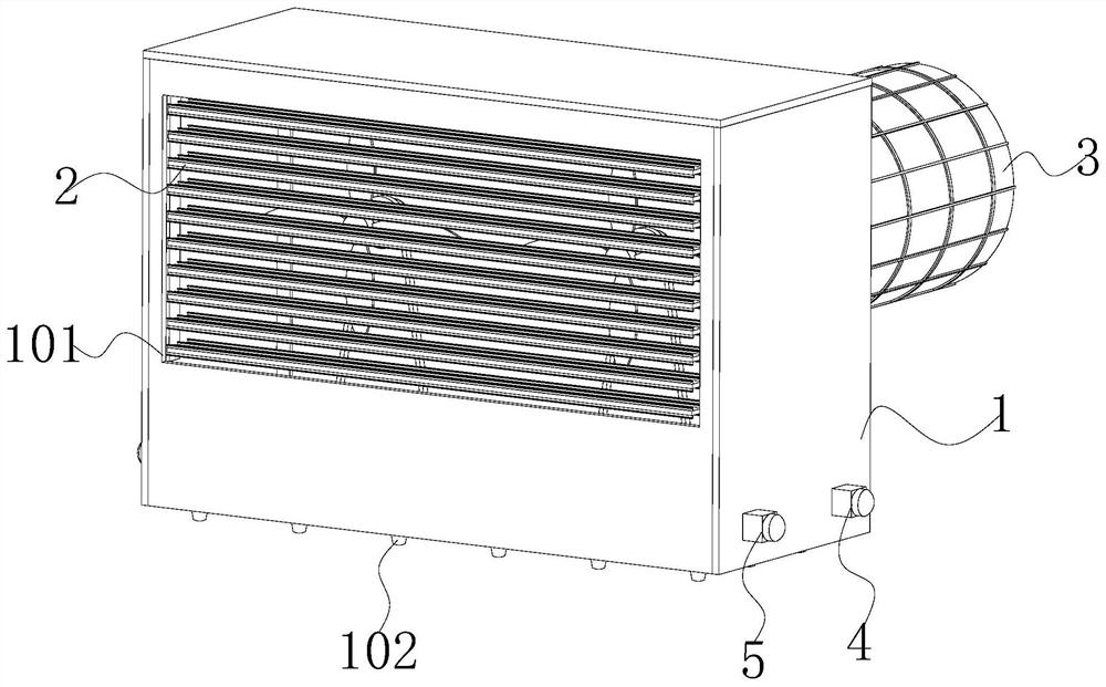
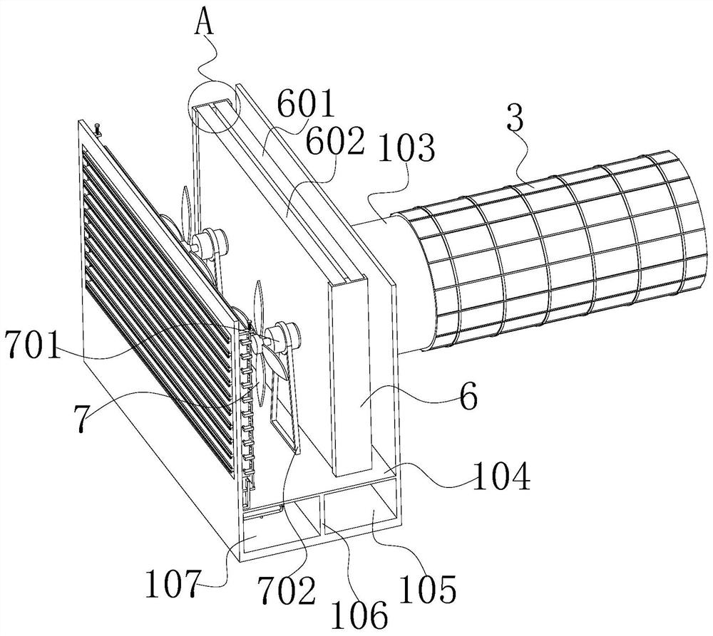
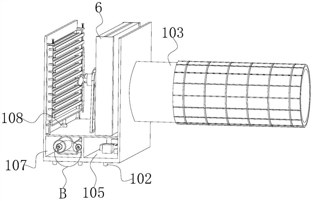
[0043] see Figure 1-3 As shown, the present invention is an environment-friendly smoke exhaust device based on building fire protection, comprising a casing 1 and an air guide window 2, and a support plate 104 is fixedly connected to the inner wall of the inner lower end of the casing 1; the support plate 104 is provided for The interior of the casing 1 is separated in the vertical direction, a mounting slot 101 is provided on the front side plate of the casing 1 above the support plate 104, and an exhaust pipe 103 is connected to the rear side plate of the casing 1 above the support plate 104; The setting of the air duct 103 is used for the discharge of smoke, and the outer wall of the exhaust duct 103 is fixedly sleeved with the solar cell panel 3, and the setting of the solar cell panel 3 can convert light energy into electrical energy during use for the electrical components of the device Using power supply, the left and right side plates and the upper side plates of the ...

Embodiment 2

[0060] Based on the environment-friendly smoke exhaust device for building firefighting described in the first embodiment, the solar panel 3 is installed on the exhaust duct 103 located outside the building. Play the role of thermal protection.

[0061] In addition, based on the electrical components in the first embodiment, the battery 14, the normally open main contact of the contactor 13, the thermal relay 12, the motor 701 or the electric telescopic rod 205 constitute two independent primary circuits, the fuse 11, the temperature Sensor 4, smoke detection sensor 5, coil of contactor 13, solenoid valve 803, microcontroller 10, and normally closed contacts of thermal relay 12 form a secondary circuit. When smoke detection sensor 5 detects that the smoke concentration reaches a certain value, the microcontroller 10 will control the secondary circuit to be turned on. When the secondary circuit is energized, the coil of the contactor 13 is energized to generate magnetism, so th...


PUM


Abstract

The invention discloses an environment-friendly smoke exhaust device based on building fire protection, and relates to the technical field of building fire protection. The device comprises a shell andan air guide window, wherein a supporting plate is fixedly connected to the inner wall of the lower end of the interior of the shell; a mounting groove is formed at the position, above the supportingplate, of a front side plate of the shell, and meanwhile, an exhaust pipe is connected to the position, above the supporting plate, of a rear side plate of the shell in a communicating manner; the outer wall of the exhaust pipe is fixedly sleeved with a solar cell panel; the air guide window is fixedly arranged in the mounting groove; and the air guide window comprises a plurality of air guide plates, connecting plates and a linkage plate, and the air guide plates are arranged in parallel in the vertical direction. Through arrangement of the series of structures and the cooperation of the structures, the device can rapidly exhaust smoke in a building in a large range in use, meanwhile, the device is provided with the independent power supply system, so that the working stability is high,in addition, the device can also carry out cooling fire-extinguishing protection, so that a very good role in protecting the device is achieved, and the normal use is guaranteed.

Description

technical field [0001] The invention belongs to the technical field of building fire protection, in particular to an environment-friendly smoke exhaust device based on building fire protection, which is mainly used for exhausting smoke inside buildings. Background technique [0002] The smoke exhaust device is mainly used to discharge a large amount of smoke in a timely manner when there is a fire inside the building, so as to avoid excessive smoke inside the building and cause a lot of damage to the people inside the building, and to buy a certain time for rescue operations. First, the existing The air intakes of the smoke exhaust devices are all fixed, and they can only exhaust smoke in fixed areas in the building, and the smoke exhaust efficiency is low. Secondly, most of the electricity systems of the existing smoke exhaust devices are connected to the building electricity system, but when the In the event of a fire, the entire building needs to be powered off, so that t...

Claims


Application Information

Patent Timeline
29 Jan 2021
Publication
CN112283840A
IPC
F24F7/06; F24F5/00; F24F13/15; F24F13/28; F24F11/34; F24F11/89; F24F11/63; A62C3/16; A62C37/40; A62C99/00; F24F110/10; F24F110/65
CPC
A62C3/16; A62C37/40; A62C99/0027; F24F5/0046; F24F7/065; F24F13/1413; F24F13/1426; F24F13/15
Inventors
汤丹