Design method for solving inconsistent highlight of vehicle body profile
A design method and body technology, applied in special data processing applications, geometric CAD and other directions, can solve the problems of time-consuming and labor-intensive, low work efficiency, uncontrollable profile quality, etc., to avoid half-way rework, save manpower, shorten The effect of the project cycle
- Summary
- Abstract
- Description
- Claims
- Application Information
AI Technical Summary
Problems solved by technology
Method used
Image
Examples
Embodiment 1
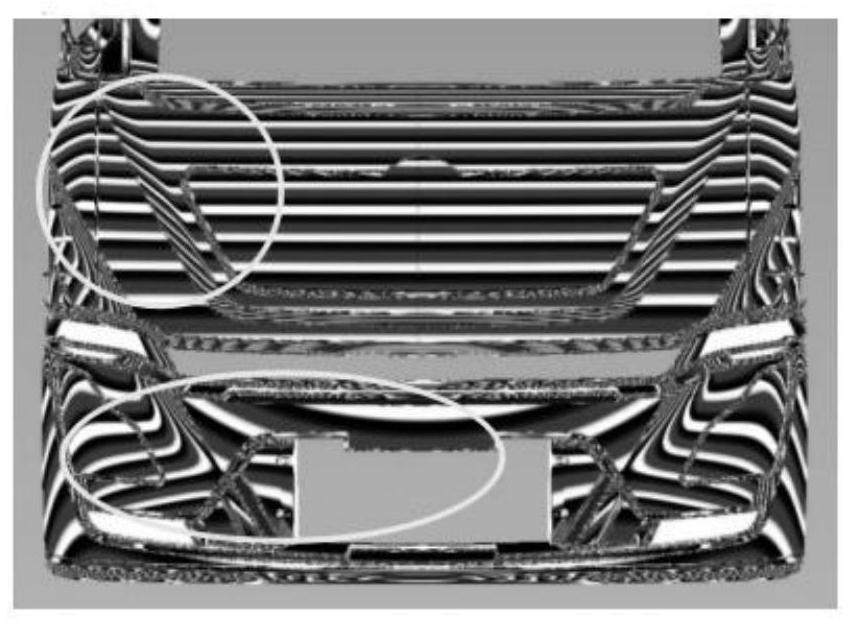
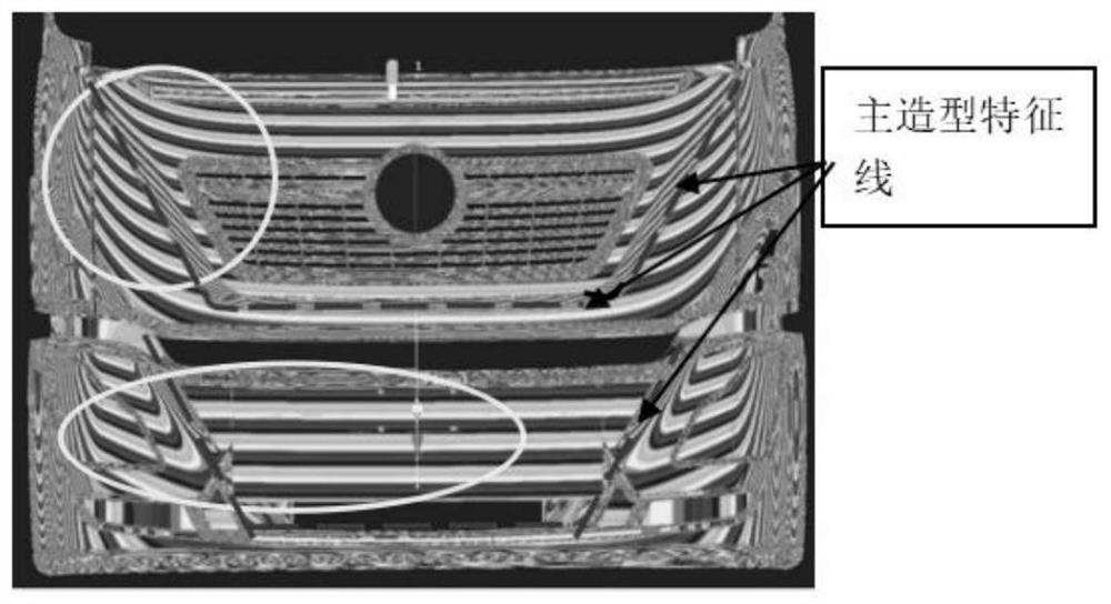
[0040] Such as figure 1 As shown, there is no relationship between the front mask and the highlight trend of the bumper profile. The mask system is straight from the middle and then descends to both ends. figure 2 shown).
Embodiment 2
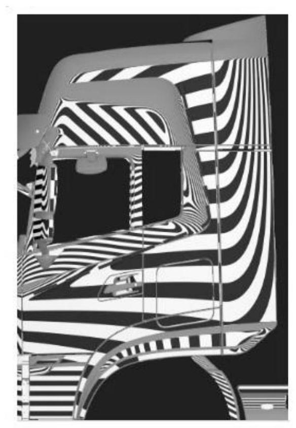
[0042] D320 side wall system profile highlight trend gradually descends from the front of the car to the rear of the car (such as image 3 As shown), from the perspective of modeling concept, the highlight trend should be consistent with the trend of the main shape feature line (waist line, side contour line). The trend remains the same (such as Figure 4 As shown); in terms of surface feeling, light and shadow flow freely with the characteristics of the body, regular and orderly, gorgeous and colorful, and the quality of the surface is good, while the latter picture is obviously better than the former.
Embodiment 3
[0044] Step 1: Taking the basic surface of the mask as an example, the initial light and shadow are as follows Figure 5 As shown (the light source for each step in the future is in the Z direction, and the Z-direction light source is very important for the high-gloss inspection of the surface quality), according to the light and shadow effect, it shows that U\V are straight and have no radians and no characteristic changes. The surface design rules require U, The V direction requires radians to ensure that the appearance parts are full and powerful.
[0045] The second step: if Figure 6 Light and shadow, pull up along the Z direction according to the two control points (select) arranged horizontally in the U direction of the profile. The size of the pull-up vector can be determined according to the light and shadow changes and the designer's expectations for the light and shadow. The control point vector is attenuated as a whole Change, the V-direction flat arc is 1mm (cont...
PUM
 Abstract
Description
Claims
Application Information
 - R&D
- Intellectual Property
- Life Sciences
- Materials
- Tech Scout
- Unparalleled Data Quality
- Higher Quality Content
- 60% Fewer Hallucinations
Browse by: Latest US Patents, China's latest patents, Technical Efficacy Thesaurus, Application Domain, Technology Topic, Popular Technical Reports.
© 2025 PatSnap. All rights reserved.Legal|Privacy policy|Modern Slavery Act Transparency Statement|Sitemap|About US| Contact US: help@patsnap.com


