Anti-bedsore sickbed

A technology for hospital beds and bedsores, which is applied in the field of special beds for preventing bedsores, can solve the problems of secondary injury of patients and difficulty in controlling the force of turning over, so as to achieve high comfort, reduce long bedsores, and avoid the effects of oppression.

Active Publication Date: 2021-02-02
THE FIRST AFFILIATED HOSPITAL OF ARMY MEDICAL UNIV
View PDF10 Cites 2 Cited by
  • Summary
  • Abstract
  • Description
  • Claims
  • Application Information

AI Technical Summary

Problems solved by technology

[0003] The present invention intends to provide an anti-decubitus bed to solve the problem that at present, in order to prevent patients from developing decubitus, it is necessary for the family members of the patients or medical staff to turn the patients over, but the force of turning over is difficult to control, and the patients are prone to secondary injuries. question

Method used


Image

  • Anti-bedsore sickbed
  • Anti-bedsore sickbed
  • Anti-bedsore sickbed

Examples


Embodiment 1

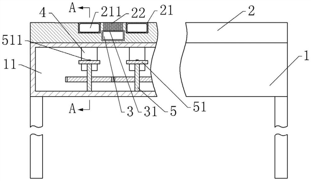
[0037] An anti-decubitus bed basically as attached figure 1 As shown, including a bed body 1 and a mattress 2 arranged on the upper surface of the bed body 1, a plurality of grooves 21 are arranged at intervals along the length direction on the mattress 2, and the number of grooves 21 can be selected according to actual needs. In the example, eight grooves 21 are preferably arranged; inflatable airbags 211 are fixed in the grooves 21, and a plurality of massage balls are arranged on the surface of the inflatable airbags 211. The mattress 2 is also provided with an installation cavity between two adjacent grooves 21. An air storage box 3 is provided in the installation cavity. Several through holes 31 are provided on the top of the air storage box 3. The upper surface of the mattress 2 is provided with The air guide hole 22 communicated with the through hole 31.

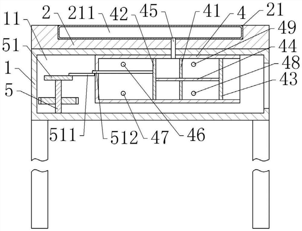
[0038] The bed body 1 is provided with a cavity 11, and the cavity 11 is provided with 8 driving parts respectivel...

Embodiment 2

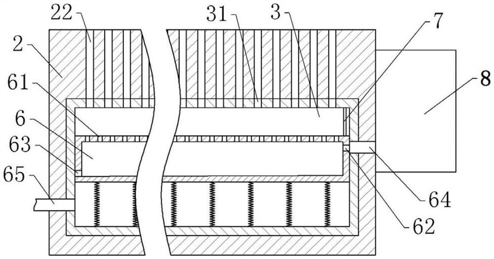
[0048] Embodiment 2 differs from Embodiment 1 only in that, as image 3 As shown, a dehumidification section is also provided in this embodiment, and the dehumidification section includes a dehumidification box 6 that is vertically slidably connected in the gas storage box 3. The specific sliding connection method is that the left and right inner walls of the gas storage box 3 are provided with To the chute, the left and right side walls of the dehumidification box 6 are respectively provided with sliders slidingly matched with the chute, and the left and right side walls of the dehumidification box 6 are attached to the left and right inner walls of the gas storage box 3. There are multiple springs welded between the bottom of the dehumidification box 6 and the bottom of the gas storage box 3. In this embodiment, the springs use compression springs, and the specific models of the springs are selected according to actual needs. The bottom surface of the dehumidification box 6 ...


PUM


Abstract

The invention belongs to the technical field of special sickbeds for preventing bedsores, and discloses an anti-bedsore sickbed. The sickbed comprises a bed body and a mattress arranged on the bed body, and further comprises a plurality of expansion air bags sequentially arranged in the length direction of the bed body, wherein a cavity is formed in the bed body; a plurality of driving parts for driving the multiple expansion air bags to expand intermittently are arranged in the cavity; each driving part comprises a piston barrel fixed in the cavity; a piston is slidably connected to the interior of each piston barrel; each piston barrel communicates with the corresponding expansion air bag; a moving rod is hinged to each piston; a transmission rod is further hinged to the end, away from the corresponding piston, of each moving rod; a rotating shaft is further rotationally connected to the interior of the cavity; a rotating disc is coaxially fixed on the rotating shaft; each transmission rod is eccentrically fixed on the rotating disc; and a motor for driving the rotating shaft to rotate is also arranged in the cavity. The sickbed solves the problems that at present, in order to prevent the bedsores of a patient, a family member of the patient or a medical staff needs to turn over the patient, and the turnover action force is not easy to control, so that secondary injury of thepatient is likely to happen.

Description

technical field [0001] The invention belongs to the technical field of special beds for preventing decubitus, and in particular relates to an anti-decubitus bed. Background technique [0002] Many patients need to stay in bed for a long time after the operation, which will cause the skin on the back to be pressed for a long time, and then the skin will become red and swollen and slowly develop into blisters, and then the blisters will burst, become infected, and the wound will deepen and turn purple, resulting in tissue cells ulceration , necrosis began to pus, the formation of bedsores. At present, in order to reduce the probability of decubitus ulcers in patients who are bedridden for a long time, the patients are usually turned over by their family members or medical staff. This method not only increases the workload of the patient's family members and medical staff, but also makes the turning movement difficult to control, and the patient is prone to secondary injury. ...

Claims


Application Information

Patent Timeline
Patent Type & Authority Applications(China)
IPC IPC(8): A61G7/00A61G7/057
CPCA61G7/00A61G7/05776A61G7/0573A61G7/05784
Inventor 文雯王红霞伍春燕甘泉芳李小林
Owner THE FIRST AFFILIATED HOSPITAL OF ARMY MEDICAL UNIV
Why Eureka
Try Eureka