Novel micro-pipettor

A technology of micropipettes and pipettes, applied in the direction of measuring tubes/pipettes, laboratory utensils, chemical instruments and methods, etc., which can solve the problems of excessive suction back, economic loss, liquid suction inside the pipette, etc. Problems, to achieve the effect of smooth adjustment process, improve accuracy, and improve the practicability of the device

Inactive Publication Date: 2021-02-02
上海唯问生物技术有限公司
View PDF4 Cites 2 Cited by
  • Summary
  • Abstract
  • Description
  • Claims
  • Application Information

AI Technical Summary

Problems solved by technology

[0003] However, during the actual use of the micropipette, due to the high resistance of the tip of the tip and the quick release of the hand, the suction is too fast and the liquid is easily sucked into the inside of the pipette, causing the inside of the pipette to be contaminated by the solution, affecting the quality of the pipette. The accuracy of the experiment and the progress of the experiment will lead to damage to the pipette more seriously and cause unnecessary economic losses; and the pipette is a precision instrument. When using it, the operator presses the button with his thumb, and the rest of his fingers are placed on the thumb. Under the support, it is necessary to maintain the correct posture and control the strength of the grip. However, the existing pipette adopts a unified design, and the distance between the finger support and the button cannot be adjusted according to the habits of the operator and the size of the hand. As a result, discomfort such as sore fingers occurs during operation; in addition, after the existing pipette removes the liquid during use, the staff will directly carry out the next step of the experimental operation, and the pipette will be directly exposed to the air at this time , causing bacteria to enter the inside of the pipette and cause contamination, making the device less practical

Method used


Image

  • Novel micro-pipettor
  • Novel micro-pipettor
  • Novel micro-pipettor

Examples


Embodiment 1

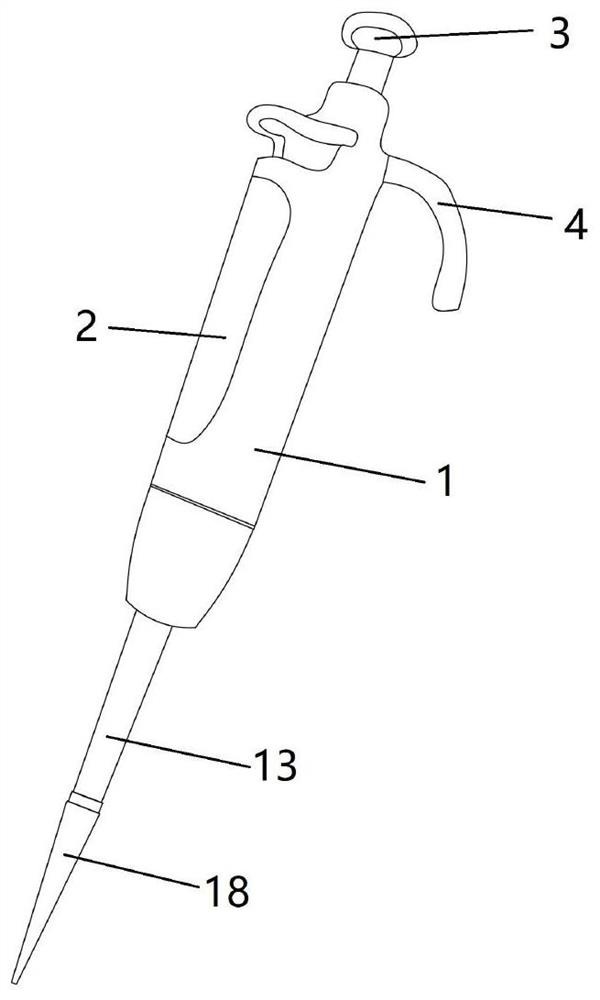
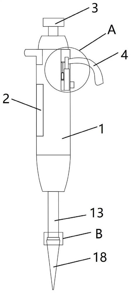
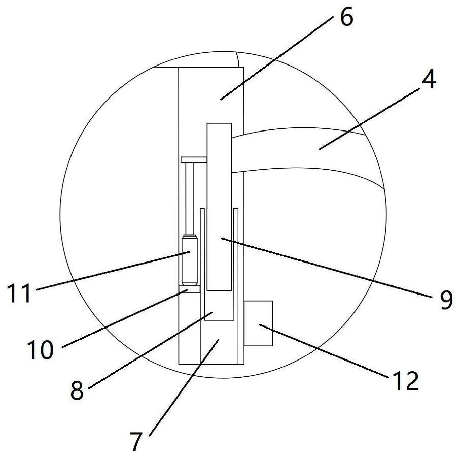
[0028] Embodiment 1 of the present invention discloses a novel micropipette, comprising a pipette main body 1, such as figure 1 and figure 2 As shown, the upper outer surface of the pipette main body 1 is equipped with a window 2, the upper end of the pipette main body 1 is provided with a pipetting button 3, and the outer surface of the pipette main body 1 is provided with a finger rest 4 near the pipetting button 3. The holder 4 is connected with the pipette main body 1 through a lifting adjustment mechanism, and a connecting pipe 13 is fixedly installed at the lower end of the pipetting main body, and the lower end of the connecting pipe 13 is connected with the suction head 18 through an anti-suckback mechanism. Such as image 3 As shown, the lifting adjustment mechanism includes a moving rod 9, a fixed rod 7 and a telescopic cylinder 11. An accommodation cavity 6 is provided on the side wall of the pipette main body 1, and a fixed rod 7 is vertically arranged at the bot...

Embodiment 2

[0031]Embodiment 2 of the present invention discloses a novel micropipette. Embodiment 2 has the same basic features as Embodiment 1, and both have the following distinguishing technical features: Figure 6 As shown, the outer surface of the lower part of the pipette body 1 is equipped with a sealing cap structure for sealing and protecting the anti-slip pipette 14. The sealing cap structure includes a cap body 19, a flexible connecting line 20 and a fixing ring 21. The fixing ring 21 is installed on the pipette. One end of the flexible connecting wire 20 is fixedly connected to the outer surface of the fixing ring 21 on the outer surface of the lower part of the liquid device main body 1 , and the other end of the flexible connecting wire 20 is connected to the outer surface of the main body 19 of the cap. The cap main body 19 is fixed on the outer surface of the pipette main body 1 through the flexible connecting wire 20 and the fixing ring 21. When the pipette is not in use,...


PUM


Abstract

The invention discloses a novel micro-pipettor which comprises a pipettor body, a window is installed on the outer surface of the upper portion of the pipettor body, a pipetting button is arranged atthe upper end of the pipettor body, a finger support is arranged at the position, close to the pipetting button, of the outer surface of the pipettor body, the finger support is connected with the pipettor body through a lifting adjusting mechanism, a connecting pipe is fixedly arranged at the lower end of the pipettor body, and the lower end of the connecting pipe is connected with a suction headthrough a suck-back prevention mechanism. The device can effectively prevent suck-back, the distance between the finger support and the button is freely adjusted according to the personal habit of anoperator and the size of the hand, and the operator feels more comfortable in operation.

Description

technical field [0001] The invention relates to the technical field of biochemical test equipment, in particular to a novel micropipette. Background technique [0002] Pipettes are used in medical, biological, biochemical, chemical and other laboratories to dose liquids. The liquid is sucked and output through the tip hole in the pipette tip. Most of the pipettes on the market are air cushion pipettes, which mainly rely on the piston in the internal cavity of the pipette to move up and down. The moving distance of the piston is adjusted by The device controls the screw structure to realize that the internal cavity of the pipette is connected with the pipette tip through the connection hole of the connecting tube, and the push button drives the push rod to move the piston downward to remove the gas in the internal cavity of the pipette. , the piston returns to its original position under the action of the return spring, and the liquid is sucked into the pipette tip and disch...

Claims


Application Information

Patent Timeline
IPC IPC(8): B01L3/02
CPCB01L3/021
Inventor 罗荣何云龙
Owner 上海唯问生物技术有限公司
Why Eureka
Try Eureka