
Stainless steel pipe machining device

A stainless steel pipe and processing device technology, which is applied in the direction of grinding drive device, metal processing equipment, grinding/polishing safety device, etc., can solve the problems of endangering one's own health, prone to safety accidents, and high labor intensity of employees, and achieves Speed ​​up the grinding efficiency, ensure the working environment, and the effect of strong practicability

Inactive Publication Date: 2021-02-02
刘丹丹
View PDF13 Cites 11 Cited by
  • Summary
  • Abstract
  • Description
  • Claims
  • Application Information

AI Technical Summary

Problems solved by technology

[0003] At present, most of the surface polishing and grinding of stainless steel pipes is to install a polishing wheel on the output shaft of the motor, and then the employee holds the stainless steel pipe and presses the surface of the stainless steel pipe against the polishing wheel for polishing, resulting in high labor intensity and low work efficiency. Low, and it is easy to cause safety accidents. In addition, a lot of noise and dust will be generated when polishing stainless steel pipes. At present, when polishing stainless steel pipes, they have not been effectively treated, which makes employees stay in their working environment for a long time. Seriously jeopardize your health when working

Method used


Image

  • Stainless steel pipe machining device
  • Stainless steel pipe machining device
  • Stainless steel pipe machining device

Examples


Embodiment Construction

[0025] In order to make the above objects, features and advantages of the present invention more comprehensible, specific implementations of the present invention will be described in detail below in conjunction with the accompanying drawings. In the following description, numerous specific details are set forth in order to provide a thorough understanding of the present invention. However, the present invention can be implemented in many other ways different from those described here, and those skilled in the art can make similar improvements without departing from the connotation of the present invention, so the present invention is not limited by the specific implementations disclosed below.

[0026] It should be noted that when an element is referred to as being “fixed” to another element, it can be directly on the other element or there can also be an intervening element. When an element is referred to as being "connected to" another element, it can be directly connected ...


PUM


Abstract

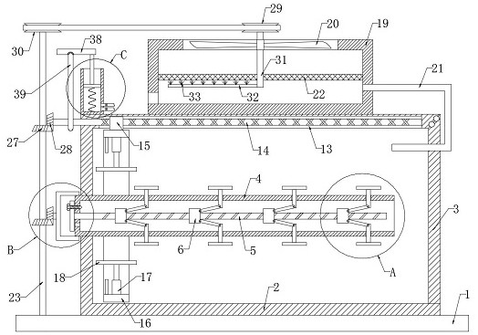
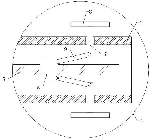
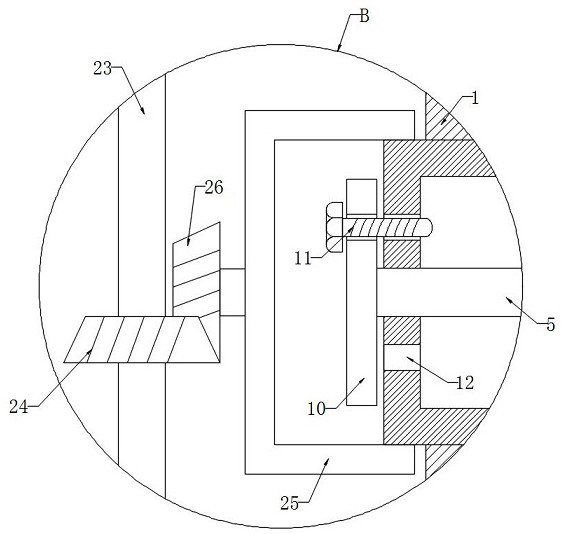
The invention discloses a stainless steel pipe machining device which comprises a base. A grinding box is fixedly connected to the upper end of the base, a box cover is hinged to the side wall of thegrinding box, a cylinder is rotatably connected to the inner wall of the grinding box, a lead screw is rotatably connected to the inner wall of the cylinder, multiple lead screw nuts are in threaded connection with the side wall of the lead screw, multiple sliding rods are symmetrically and slidably connected to the side wall of the cylinder, and clamping plates are fixedly connected to the ends,away from the lead screw, of the sliding rods. According to the stainless steel pipe machining device, the lead screw nuts slide on the side wall of the lead screw by rotating the lead screw, then thelead screw nuts drive the sliding rods to slide on the side wall of the cylinder through connecting rods, then the clamping plates are driven to slide on the side wall of the cylinder, stainless steel pipes with different pipe diameters can be clamped, and operation is easy; and when grinding plates slide on the side walls of stainless steel back and forth, the cylinder drives the clamped stainless steel pipes to rotate, then the stainless steel pipes can be comprehensively and quickly ground, and the grinding efficiency to the stainless steel pipes is improved.

Description

technical field [0001] The invention relates to the technical field of stainless steel pipe processing, in particular to a stainless steel pipe processing device. Background technique [0002] Stainless steel pipe fittings have good mechanical properties and corrosion resistance, and are widely used in aerospace, marine, nuclear energy, medical equipment, petrochemical and other fields. During pipe processing, in order to ensure the appearance of stainless steel pipes, the surface needs to be polished and polished. [0003] At present, most of the surface polishing and grinding of stainless steel pipes is to install a polishing wheel on the output shaft of the motor, and then the employee holds the stainless steel pipe and presses the surface of the stainless steel pipe to the polishing wheel for polishing, which leads to greater labor intensity and lower work efficiency. low, and it is easy to cause safety accidents. In addition, a lot of noise and dust will be generated w...

Claims


Application Information

Patent Timeline
Patent Type & Authority Applications(China)
IPC IPC(8): B24B5/04B24B41/06B24B47/00B24B47/12B24B47/16B24B55/06B24B55/12B01D46/00B01D46/10
CPCB24B5/045B24B41/067B24B47/00B24B47/16B24B47/12B24B55/06B24B55/12B01D46/10B01D46/681
Inventor 刘丹丹
Owner 刘丹丹
Learn More