Variable-rigidity joint system based on air cylinder

A technology of variable stiffness and cylinder, applied in the field of robots, can solve the problems of many parts, large joint size, narrow joint deformation range, etc., and achieve the effect of reducing joint weight, reducing joint size and improving efficiency.

Active Publication Date: 2021-02-02
BEIJING UNIV OF POSTS & TELECOMM
View PDF5 Cites 0 Cited by
  • Summary
  • Abstract
  • Description
  • Claims
  • Application Information

AI Technical Summary

Problems solved by technology

The main problem with antagonistic variable stiffness joints is that the range of joint deformation narrows as the stiffness of the system increases
The main problem of the variable transmission rate variable stiffness joint is: in order to realize the variable transmission rate function, the joint size is large and many parts are used

Method used


Image

  • Variable-rigidity joint system based on air cylinder
  • Variable-rigidity joint system based on air cylinder
  • Variable-rigidity joint system based on air cylinder

Examples


Embodiment Construction

[0023] The present invention will be further described in detail with reference to the accompanying drawings and embodiments.

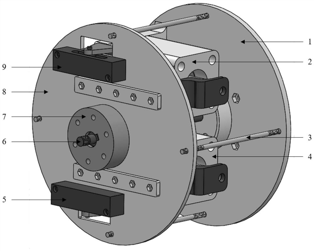
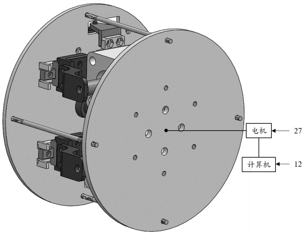
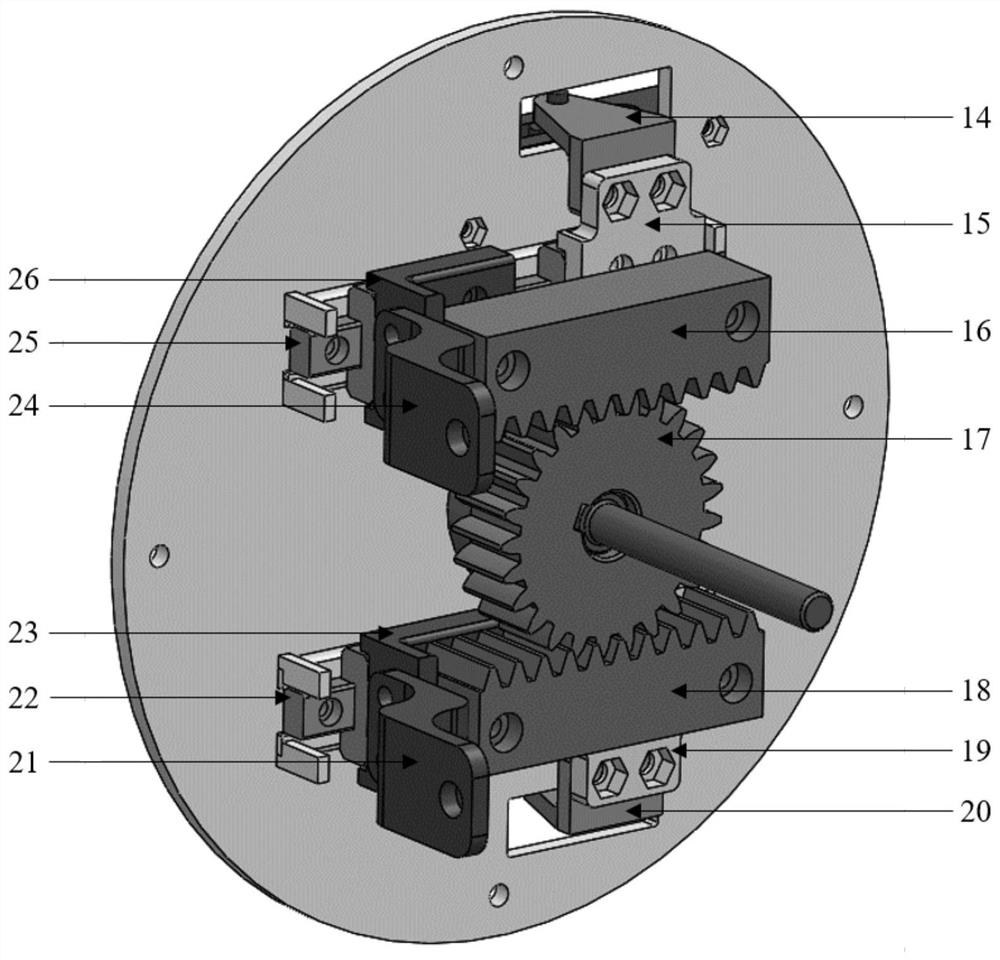
[0024] The present invention is a cylinder-based variable stiffness joint system, such as figure 1 As shown, it includes: cylinder support plate 1, upper cylinder 2, support plate connecting rod 3, lower cylinder 4, lower linear displacement sensor 5, transmission spindle 6, arm connection block 7, rack support plate 8, upper linear displacement sensor 9 , upper proportional valve 10, air source 11, computer 12, lower proportional valve 13, upper sensor connection block 14, upper sensor connection base 15, upper rack 16, transmission gear 17, lower rack 18, lower sensor connection base 19, Lower sensor connection block 20, lower cylinder connection block 21, lower linear guide rail 22, lower cylinder connection base 23, upper cylinder connection block 24, upper linear guide rail 25, upper cylinder connection base 26, motor 27;

[0025] The cylinder-b...


PUM


Abstract

The invention discloses a variable-rigidity joint system based on an air cylinder. The joint system comprises an air cylinder supporting disc 1, an upper air cylinder 2, a supporting disc connecting rod 3, a lower air cylinder 4, a lower linear displacement sensor 5, a transmission main shaft 6, an arm connecting block 7, a rack supporting disc 8, an upper linear displacement sensor 9, an upper proportional valve 10, an air source 11, a computer 12, a lower proportional valve 13, an upper sensor connecting block 14, an upper sensor connecting base 15, an upper rack 16, a transmission gear 17,a lower rack 18, a lower sensor connecting base 19, a lower sensor connecting block 20, a lower air cylinder connecting block 21, a lower linear guide rail 22, a lower air cylinder connecting base 23,an upper air cylinder connecting block 24, an upper linear guide rail 25, an upper air cylinder connecting base 26 and a motor 27. According to the variable-rigidity joint system, the upper air cylinder and the lower air cylinder can effectively solve the problem that the joint deformation range of an antagonistic variable-rigidity joint is seriously limited when the rigidity is high. The outputtorque precision is high, the rigidity regulation and control range is wide, and the dynamic response performance is excellent.

Description

technical field [0001] The invention relates to a robot joint with variable stiffness, which belongs to the technical field of robots, in particular to the structural design of robot components. Background technique [0002] At present, the mechanism design of variable stiffness robot joints is mainly divided into three categories, antagonistic mechanism, single spring mechanism and variable transmission rate mechanism. The principle adopted by the antagonistic variable stiffness joint to adjust the stiffness is mainly as follows: multiple elastic elements are connected in parallel and pull each other to change the preload force of the joint at the equilibrium position. The main problem with antagonistic variable stiffness joints is that the range of joint deformation narrows as the stiffness of the system increases. The principle adopted by the single spring type variable stiffness joint to adjust the stiffness is mainly to change the preload force of the joint by pulling ...

Claims


Application Information

Patent Timeline
Patent Type & Authority Applications(China)
IPC IPC(8): B25J17/00B25J9/10B25J9/14B25J19/00
CPCB25J17/00B25J9/14B25J9/1035B25J19/00
Inventor 吴昊城苏柏泉刘了了闫昊姚炜刘文勇
Owner BEIJING UNIV OF POSTS & TELECOMM
Why Eureka
Try Eureka