Slicing machine for sesame seed candy production
A technology of sesame candy and slicing machine, which is applied in the direction of metal processing, etc., can solve the problems of low work efficiency, time-consuming and labor-intensive sesame candy, uneven thickness of sesame candy, etc., and achieve the effect of improving work efficiency
- Summary
- Abstract
- Description
- Claims
- Application Information
AI Technical Summary
Problems solved by technology
Method used
Image

Examples
Embodiment 1
[0085] A kind of slicer for sesame candy production, such as figure 1 As shown, it includes a bottom plate 1, a workbench 2, a motor 3, a material cutting mechanism 4, a blanking mechanism 5, a transmission mechanism 6, and a shredding mechanism 7. The top of the bottom plate 1 is provided with a workbench 2, and the front side of the top of the workbench 2 is on the right side. A motor 3 is provided at the top of the workbench 2, a cutting mechanism 4 is arranged in the middle of the top of the workbench 2, a cutting mechanism 5 is arranged on the left side of the top of the workbench 2, a transmission mechanism 6 is arranged on the front side of the top of the workbench 2, and the left side of the top of the workbench 2 is connected to the A shredding mechanism 7 is arranged between the transmission mechanism 6, and the shredding mechanism 7 is on the left side of the blanking mechanism 5.
[0086] When people need to use this device to cut the sesame candy, put the sesame c...
Embodiment 2
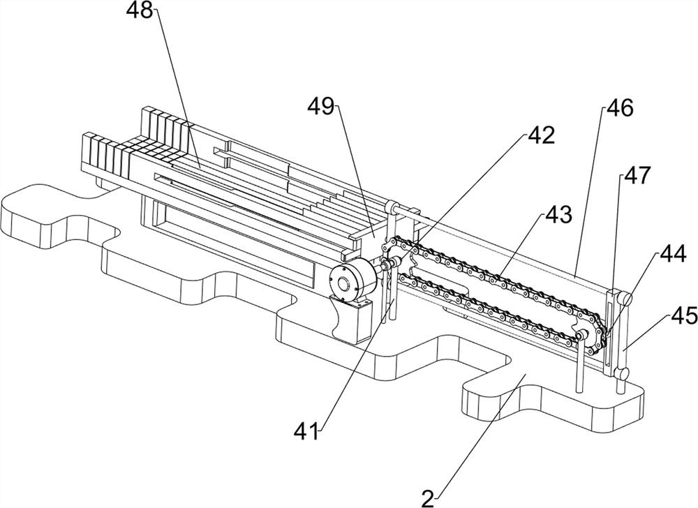
[0088] On the basis of Example 1, such as figure 2 , image 3 , Figure 4 , Figure 5 with Image 6 As shown, the material cutting mechanism 4 includes a first column sleeve 41, a first rotating shaft 42, a first transmission device 43, a connecting column 44, a fixed rod 45, a slideway rod 46, a first sliding block 47, a cutting concave plate 48 and Cutting knife 49, the left and right sides of the top of the workbench 2 are symmetrically provided with a first column sleeve 41, and the first column sleeve 41 is equipped with a first rotating shaft 42 in a rotating manner, and a first transmission device 43 is arranged between the first rotating shaft 42. The first transmission device 43 is a sprocket wheel and a chain transmission, and the front end of the first rotating shaft 42 on the left side is connected with the output shaft of the motor 3. The left and right sides of the top of the workbench 2 are symmetrically provided with a fixed rod 45, and the fixed rod 45 is ...
Embodiment 3
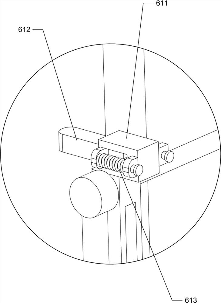
[0093] On the basis of Example 2, such as figure 1 , Figure 7 , Figure 8 , Figure 9 , Figure 10 with Figure 11 As shown, the transmission mechanism 6 includes a second guide block 61, a second column sleeve 62, a first sliding rod 63, a long plate 64, a guide rail 65, a first spur rack 66, a second compression spring 67, a first Three post sets 68, the second rotating shaft 69, the first straight gear 691, the bevel gear set 610, the third guiding block 611, the third sliding block 612 and the third compression spring 613, the top of the first sliding block 47 is provided with a third Guide block 611, the front side of the third guide block 611 is slidingly provided with a third slide block 612, and a third compression spring is arranged between the left and right sides of the rear side of the third slide block 612 and the third guide block 611 613, the third compression spring 613 is set on the third sliding block 612, the right part of the front side of the top of ...
PUM
 Abstract
Description
Claims
Application Information
 - R&D Engineer
- R&D Manager
- IP Professional
- Industry Leading Data Capabilities
- Powerful AI technology
- Patent DNA Extraction
Browse by: Latest US Patents, China's latest patents, Technical Efficacy Thesaurus, Application Domain, Technology Topic.
© 2024 PatSnap. All rights reserved.Legal|Privacy policy|Modern Slavery Act Transparency Statement|Sitemap