
Conveying positioning device for sagger visual inspection

A visual inspection and positioning device technology, applied in the direction of conveyor objects, transportation and packaging, optical testing defects/defects, etc., can solve the problems of peeling and slag, waste of defective materials, misjudgment and missed judgment, etc., to achieve the goal of conveying High efficiency, the effect of improving the overall production efficiency

Pending Publication Date: 2021-02-02
SHANGHAI LUDA PACKING MACHINERY CO LTD
View PDF0 Cites 4 Cited by
  • Summary
  • Abstract
  • Description
  • Claims
  • Application Information

AI Technical Summary

Problems solved by technology

In the entire kiln firing production line, the sagger is a recyclable charging container. Due to the high temperature during the firing process, the sagger is frequently subjected to sudden cooling and heat, and the material itself may have an impact on the sagger , leading to a short service life of the sagger, prone to cracks, defects, peeling and slag, large residues of materials, etc., and this kind of sagger will no longer be used for charging and firing
[0003] At present, the quality of the saggar is mostly checked manually, or the detection of the sagger in the use of the roller furnace mainly relies on manual observation of the appearance of the sagger, and the ambient temperature around the roller furnace is high and 24 hours a day. It is easy to cause misjudgment and missed judgment, and the cost is high, the efficiency is low, and it is easy to cause the generation of defective products and the waste of materials.
Moreover, if unqualified saggers enter the kiln for firing, it will cause great harm

Method used


Image

  • Conveying positioning device for sagger visual inspection
  • Conveying positioning device for sagger visual inspection
  • Conveying positioning device for sagger visual inspection

Examples


Embodiment Construction

[0030] The present invention is further described below by way of examples, but the present invention is not limited to the scope of the described examples.

[0031]

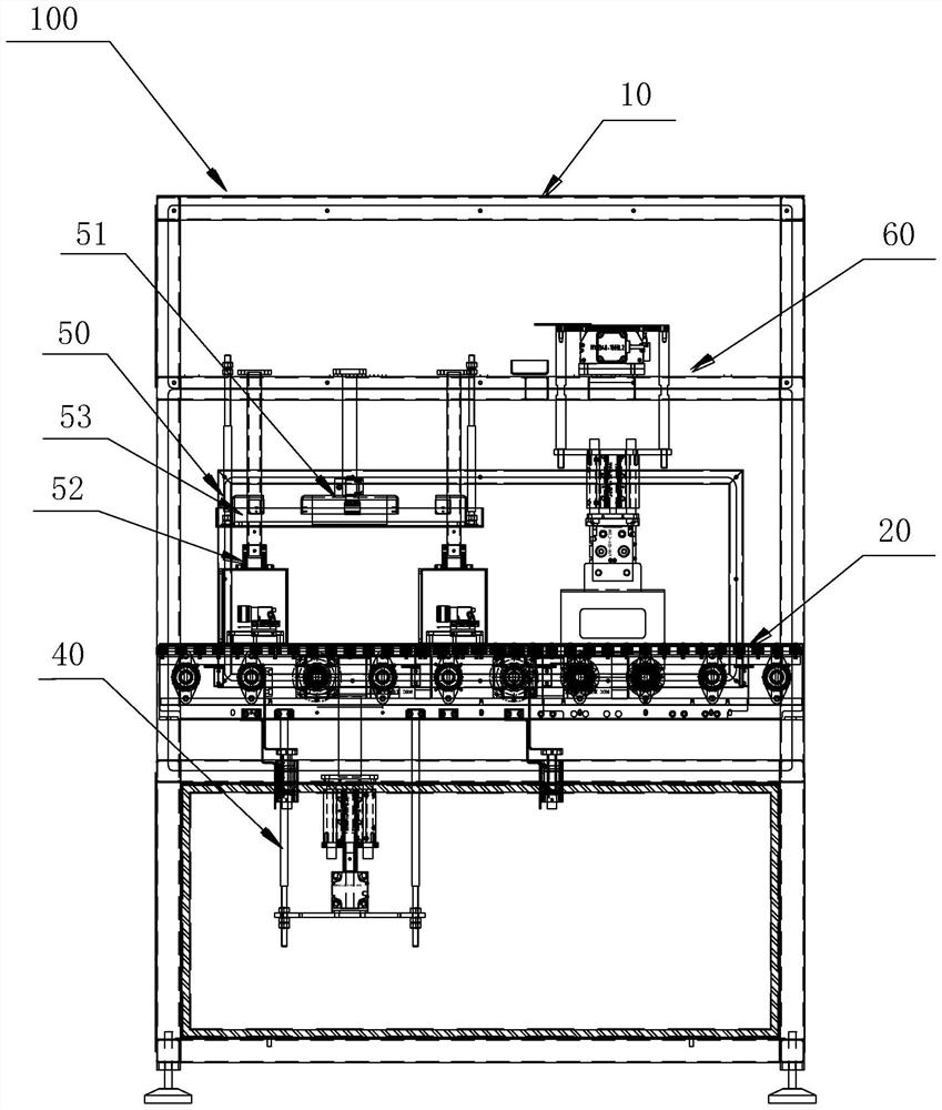
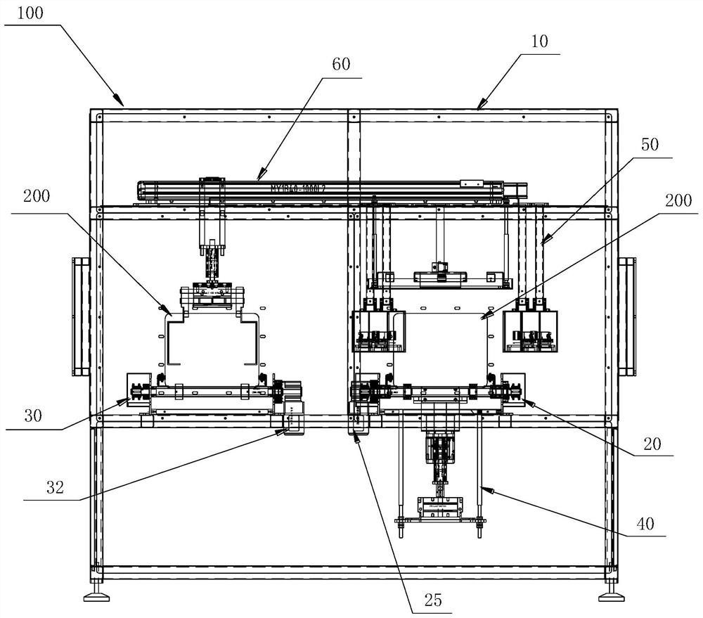
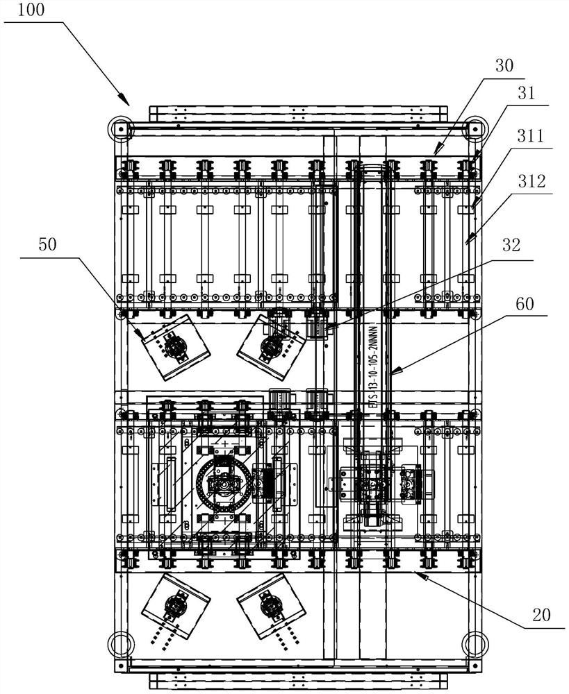
[0032] like Figures 1 to 10 As shown, this embodiment discloses a saggar visual inspection equipment 100, which is mainly used for special equipment for crack detection and rejection of the saggar 200 used for special materials. Crack detection, defect detection, peeling and slag detection, and bulk residue detection are carried out in the bowl, so as to remove the unqualified saggars 200. The whole detection and rejection process is fast, efficient, and precisely controlled. Especially when detecting the AB bowl, it can also perform the filling operation. Based on this, after the saggar visual inspection device 100 is applied in an automated production line, for example, an entire automated assembly line is formed by supporting a bowl filling machine, a shaker, a bowl stacking machine, a conveyor, etc., whi...


PUM


Abstract

The invention provides a conveying and positioning device for sagger visual inspection. The conveying and positioning device comprises a conveying unit and a jacking unit, wherein the conveying unit is used for conveying saggers in a preset conveying direction, and forming a detection region on a conveying path; the jacking unit is arranged below the conveying unit corresponding to the detection region, can penetrate through the conveying unit to be arranged in a lifting manner and is used for jacking the saggers to be separated from the conveying unit and reach a detection station so that a detection unit in sagger visual detection equipment can conveniently conduct visual detection treatment on the saggers to judge whether the quality of the saggers is qualified or not; and after detection is completed, the jacking unit descends to enable the saggers to be transferred to the conveying unit to be continuously conveyed, and automatic conveying before and after sagger quality detectionis completed through the process, so that the conveying efficiency is high; and the saggers are quickly and accurately conveyed to the detection station, so that the overall production efficiency of sagger visual detection equipment is improved.

Description

technical field [0001] The invention belongs to the technical field of automated production lines, and in particular relates to a conveying and positioning device for visual inspection of a saggar. Background technique [0002] Saggar is a kind of kiln furniture made of refractory material, which is used to contain powder materials into the kiln for firing, and then the saggar contains powder materials and leaves the kiln together. After the materials are broken, the powder materials are poured out of the saggar, and the empty saggar is cleaned and then charged and fired again. In the entire kiln firing production line, the saggar is a recyclable charging container. Due to the high temperature during the firing process, the saggar is frequently subjected to sudden cooling and sudden heating, and the material itself may have an impact on the saggar. , resulting in a short service life of the saggar, prone to cracks, defects, peeling and slag, and large residues of materials,...

Claims


Application Information

Patent Timeline
IPC IPC(8): B65G47/24G01N21/88
CPCB65G47/24G01N21/88
Inventor 姚轶纬李桂明
Owner SHANGHAI LUDA PACKING MACHINERY CO LTD
Learn More