Supercharge Your Innovation With Domain-Expert AI Agents!

Automatic Z-direction fiber implantation device for composite material preform

A technology of composite materials and implanted devices, which is applied in the direction of textiles, papermaking, braided fabrics, weight reduction, etc., can solve the problems of expensive labor costs, high labor intensity, and low production efficiency, so as to improve the quality and efficiency of forming, and improve work efficiency. Efficiency, quality improvement effect

Active Publication Date: 2021-02-02
ADVANCED MFG TECH CENT CHINA ACAD OF MASCH SCI & TECH
View PDF6 Cites 1 Cited by
  • Summary
  • Abstract
  • Description
  • Claims
  • Application Information

AI Technical Summary

Problems solved by technology

At present, after the composite material preform is woven, there are still array steel needles formed in a certain regular shape array in the Z direction, and the array steel needles need to be replaced by Z-direction fibers, but the process of introducing Z-direction fibers is still manual.
This Z-direction fiber introduction method has high labor intensity, low production efficiency, and high labor cost. Moreover, due to the contact between the human hand and the fiber and the friction between the fiber and the traditional yarn replacement needle, the quality of the fiber is reduced, which affects the quality of the yarn. The overall quality of the preform
Therefore, manual introduction of Z-direction fibers into three-dimensional fabrics can no longer meet the needs of the market, and there is an urgent need for an automatic Z-direction fiber implantation device for composite material prefabricated bodies to complete automated production

Method used


Image

  • Automatic Z-direction fiber implantation device for composite material preform
  • Automatic Z-direction fiber implantation device for composite material preform
  • Automatic Z-direction fiber implantation device for composite material preform

Examples


Embodiment Construction

[0035] The present invention will be described in further detail below in conjunction with specific embodiments.

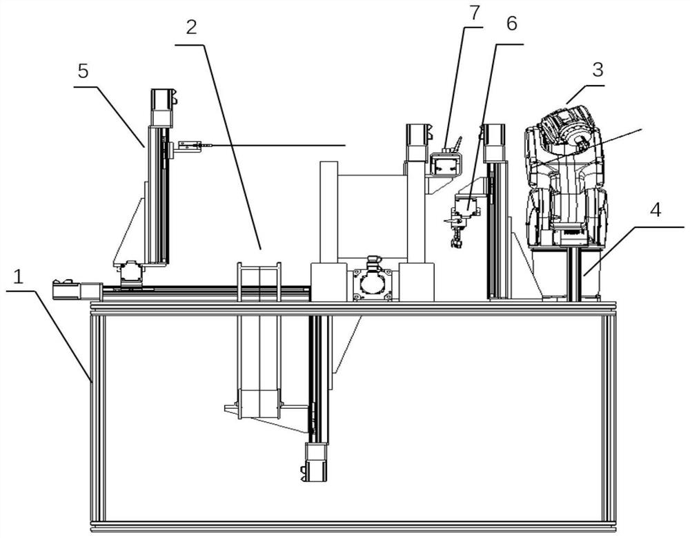
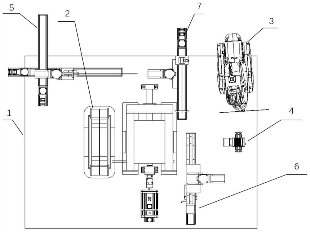
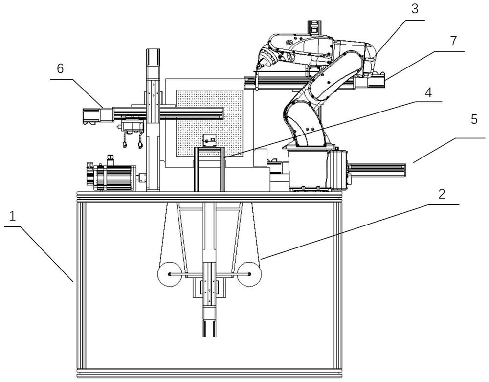
[0036] Such as Figure 1 to Figure 8 As shown, for prefabricated bodies of different sizes, the minimum array needle diameter is 1.2 mm, and the minimum array needle center distance is 2.4 mm. A Z-direction fiber replacement method and device are designed, including a workbench 1 and a yarn lifting mechanism 2; Yarn needle conveying mechanism 3, visual positioning mechanism 4, array steel needle clamping mechanism 5, wire loop forming mechanism 6, metal rod conveying mechanism 7, said workbench 1 includes workpiece clamping mechanism 101, servo motor 102, bearing 103, The yarn lifting mechanism 2 includes a mobile module 201, a yarn roller 202, the yarn replacement needle delivery mechanism 3 includes a mechanical arm structure 301, a yarn replacement needle clamping mechanism 302, and a yarn replacement needle 303, and the visual positioning mechanism 4 includes ...


PUM


Abstract

The invention designs an automatic Z-direction fiber implantation device for a composite material preform, and belongs to the technical field of advanced manufacturing. A process comprises the following steps that a yarn replacing needle is moved to a three-dimensional fabric array steel needle under the clamping of a clamping mechanism on a mechanical arm, an array steel needle replacing processis finished under the combined action of the yarn replacing needle and the array steel needle clamping mechanism, a lifting yarn frame is designed on one side of three-dimensional fabric and controlled by tension to be in a tensioned state, Z-direction fibers of the three-dimensional fabric are led in by hooking yarn through the yarn replacing needle, yarn rings are formed after the Z-direction fibers are led in, the diameter of the yarn rings is increased through a yarn ring forming mechanism, a metal rod carrying the yarn is moved to the yarn rings through a metal rod conveying mechanism, after the metal rod penetrates through a row of yarn rings, the metal rod is taken out along the yarn rings, the yarn is left in the yarn rings, and therefore sewing of the three-dimensional fabric is completed. According to the automatic Z-direction fiber implantation device for the composite material preform, the accuracy and the working efficiency of the Z-direction fiber introduction process areimproved.

Description

technical field [0001] The invention designs a composite material prefabricated body Z-direction fiber automatic implantation device, which belongs to the field of advanced manufacturing technology. Background technique [0002] Composite components are widely used in aerospace, military and other fields, so the requirements for the structure and performance of composite materials are also constantly increasing. Compared with two-dimensional composite components, three-dimensional structural composite components introduce reinforcing fibers in the Z direction to improve The interlayer strength in the thickness direction of the carbon fiber three-dimensional fabric is improved, and the problems of easy delamination of composite components, low impact toughness and damage tolerance are solved. At present, after the composite material preform is woven, there are still array steel needles formed in a certain regular shape array in the Z direction, and the array steel needles nee...

Claims


Application Information

Patent Timeline
IPC IPC(8): D04C3/00
CPCD04C3/00Y02T50/40
Inventor 单忠德郭子桐战丽李思源刘云志刘阳李军
Owner ADVANCED MFG TECH CENT CHINA ACAD OF MASCH SCI & TECH
Features
  • R&D
  • Intellectual Property
  • Life Sciences
  • Materials
  • Tech Scout
  • Unparalleled Data Quality
  • Higher Quality Content
  • 60% Fewer Hallucinations
Learn More