River channel sludge cleaning device

A cleaning device and river silt technology, which is applied in the direction of earth movers/shovels, mechanically driven excavators/dredgers, construction, etc., can solve the problems of poor dredging effect and inability to ensure effective cleaning of silt deep in the river bed , to achieve the effect of ensuring quality and efficiency

Inactive Publication Date: 2021-02-02
王红艳
View PDF9 Cites 8 Cited by
  • Summary
  • Abstract
  • Description
  • Claims
  • Application Information

AI Technical Summary

Problems solved by technology

[0006] Aiming at the deficiencies of the prior art, the present invention provides a river channel silt cleaning device, which solves the problem that the traditional dredging equipment will stir and clean the sludge when it is working, so that a large amount of sludge will flow downstream with the river water, causing sedimentation of downstream riverbed sludge and dredging effect Poor, and the traditional equipment can not go deep into the silt for cleaning, thus can not guarantee the effective cleaning of the silt deep in the river bed

Method used


Image

  • River channel sludge cleaning device
  • River channel sludge cleaning device
  • River channel sludge cleaning device

Examples


Embodiment 1

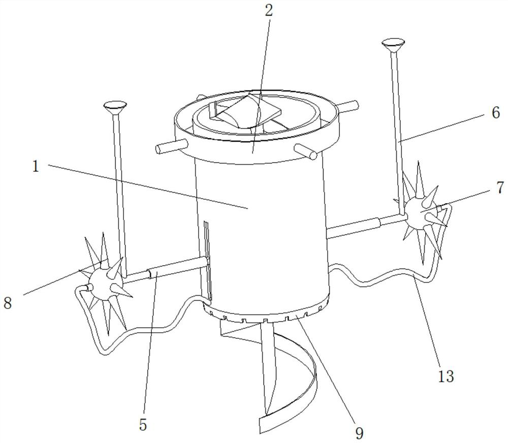
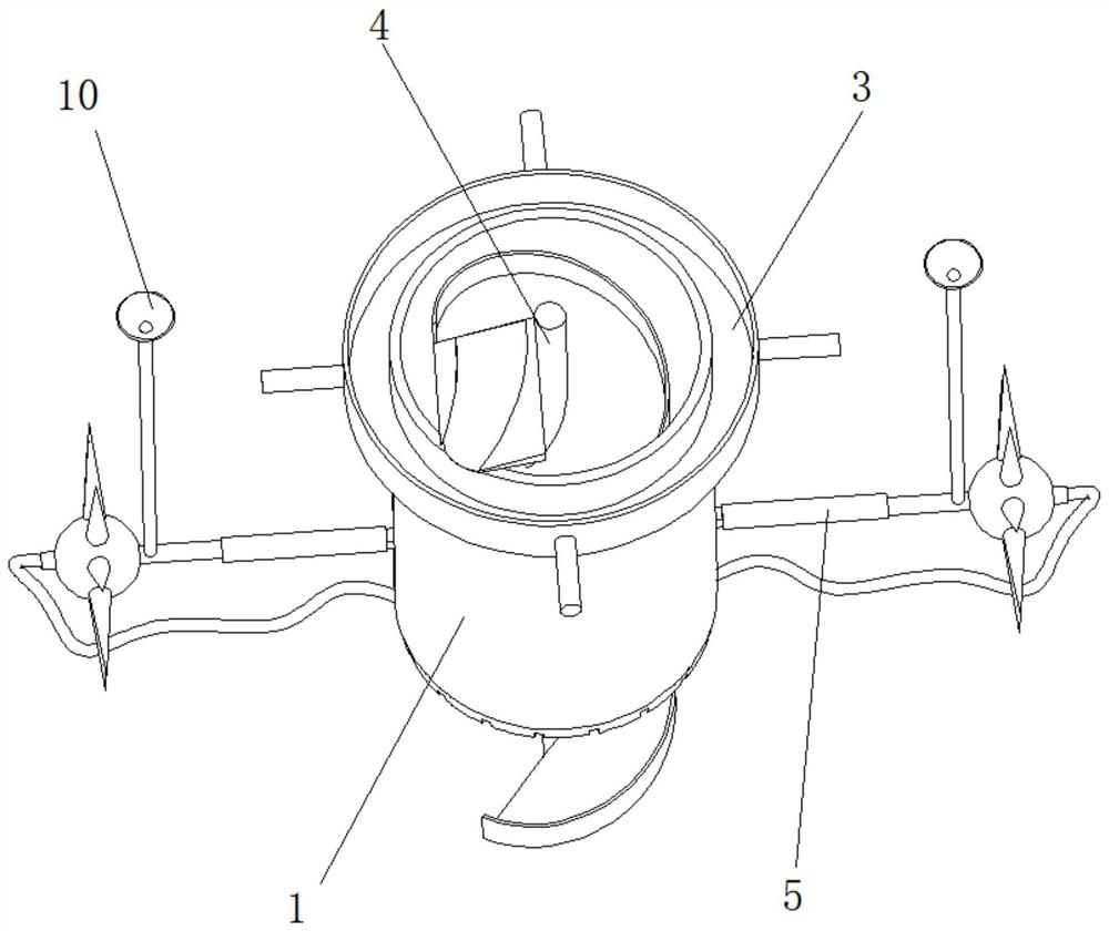
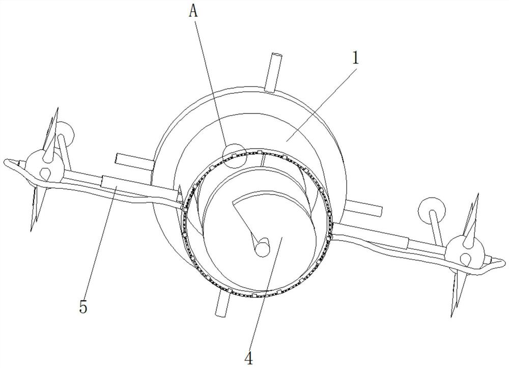
[0038] Such as Figure 1-4 As shown, the present invention provides a technical solution: a river channel silt cleaning device, including a cleaning limiting barrel 1, the top of the cleaning limiting barrel 1 is fixedly connected with a driving disc 2, and the top of the driving disc 2 is fixedly connected with a storage inner Groove 3, the vertical middle position inside the cleaning and limiting barrel 1 is provided with a coupling drive mechanism 4, and the external sides of the cleaning and limiting barrel 1 and the positions near the bottom are slidingly connected with the driving auxiliary mechanism 5, and the input end of the driving auxiliary mechanism 5 is fixed. Connected with a liquid level air guide tube 6, the drive auxiliary mechanism 5 is fixedly connected to the outer side of one end away from the cleaning restriction barrel 1. A walking ball 7 is fixedly connected to the outer surface of the walking ball 7. The outer surface of the walking ball 7 is uniformly ...

Embodiment 2

[0042] Such as Figure 5-7 As shown, on the basis of Embodiment 1, the present invention provides a technical solution: a river channel silt cleaning device, the coupling drive mechanism 4 includes a cleaning rotary shaft 41, and the outer surface of the cleaning rotary shaft 41 is fixedly connected with a guide vane 42 , the outer surface of the guide vane 42 is fixedly connected with a limiting side baffle 43 .

[0043] Clean the outer upper surface of the rotating shaft 41 and be located in the middle of the guide vane 42 to be provided with a spiral chute 44, the inside of the spiral chute 44 is slidably connected with a moving slider 45, and the outer side of the moving slider 45 is fixedly connected with a transmission connecting rod 46 One end of the transmission link 46 away from the moving slider 45 is fixedly connected to the lower position inside the cleaning restriction barrel 1 .

[0044] The top of the cleaning rotary shaft 41 is fixedly connected with a materia...

Embodiment 3

[0046] Such as Figure 8 As shown, on the basis of Embodiment 1 and Embodiment 2, the present invention provides a technical solution: a river channel silt cleaning device, the driving auxiliary mechanism 5 includes a supporting driving rod 51, and the left side of the supporting driving rod 51 is connected with the cleaning device. Limit the surface sliding connection of the barrel 1, the right side of the inside of the support drive rod 51 is fixedly connected with an auxiliary plug 52, the inside of the auxiliary plug 52 runs through and is threadedly connected with a reciprocating screw rod 53, the right side of the reciprocating screw rod 53 is connected to the walking ball 7 fixed connectivity.

[0047] The inside of the reciprocating screw rod 53 is provided with a boost chamber 54, the left side of the support drive rod 51 is fixedly connected with a support insert rod 55, and the right end of the support insert rod 55 is fixedly connected with a sealing slider 56, and...


PUM


Abstract

The invention discloses a river channel sludge cleaning device. The river channel sludge cleaning device comprises a cleaning limiting barrel, wherein the top end of the cleaning limiting barrel is fixedly connected with a driving disc; the top end of the inside of the driving disc is fixedly connected with a storage inner groove; a connecting shaft driving mechanism is arranged in the vertical middle of the inside of the cleaning limiting barrel; the two sides of the outside of the cleaning limiting barrel and the positions close to the lower portion of the cleaning limiting barrel are slidably connected with driving auxiliary mechanisms; input ends of the driving auxiliary mechanisms fixedly communicate with liquid level air guiding tubes; the outer sides of the ends, which are away fromthe cleaning limiting barrel, of the driving auxiliary mechanisms are fixedly connected with traveling balls; the surfaces of the outsides of the traveling balls are uniformly and fixedly connected with limiting pins; the periphery of the bottom of the cleaning limiting barrel is fixedly connected with a propelling conical block; and the tops of the liquid level air guiding tubes are fixedly connected with floating through grooves. The invention relates to the technical field of river channels. By the river channel sludge cleaning device, to-be-cleaned sludge is framed and limited, the circumstance that the sludge is scattered to the downstream by water flow during cleaning is avoided, and the sludge cleaning quality and efficiency are ensured.

Description

technical field [0001] The invention relates to the technical field of river channel cleaning, in particular to a river channel sludge cleaning device. Background technique [0002] River dredging generally refers to the treatment of rivers, which belongs to water conservancy projects. Through mechanical equipment, the silt deposited on the bottom of the river is blown and stirred into turbid water, which flows away with the river water, thus playing the role of dredging. [0003] As the Chinese Invention Publication No.: CN104294875A, a river dredger comprises a hull, the front end of the hull is provided with a mud transporting device, and the mud transporting device includes a skeleton, and the skeleton is provided with several belts. The pulley and the motor that drives the pulley to rotate, the pulley is provided with a crawler, and the scraper is arranged on the crawler; the front end of the skeleton is provided with a grid that wraps the crawler and the scraper but d...

Claims


Application Information

Patent Timeline
Patent Type & Authority Applications(China)
IPC IPC(8): E02F5/28E02F3/88E02F3/90E02F3/92
CPCE02F5/282E02F5/287E02F3/8833E02F3/90E02F3/9218E02F3/9225
Inventor 王红艳
Owner 王红艳
Why Eureka
Try Eureka