Pipeline dredging device for smart city construction

A technology for urban construction and desilting equipment, applied in water supply equipment, cleaning sewer pipes, buildings, etc., can solve the problems of pipelines with different diameters, troublesome operation, low efficiency of manual excavation, etc., and achieve better removal effect Good, easy to scrape off, good sludge removal effect

Active Publication Date: 2021-02-02
WEIFANG BOTAI ENERGY TECH CO LTD
View PDF10 Cites 3 Cited by
  • Summary
  • Abstract
  • Description
  • Claims
  • Application Information

AI Technical Summary

Problems solved by technology

[0003] At present, most of the municipal sewer pipes are manually excavated, which is labor-intensive, and some pipelines are difficult to excavate manually after the silt is deposited, and the efficiency of manual excavation is relatively low. Traditional dredging devices use a variety of high-power devices. , the operation is cumbersome and consumes electric energy at the same time, and the existing dredging device cannot be used for pipes with different diameters. These issues are what we need to consider

Method used


Image

  • Pipeline dredging device for smart city construction
  • Pipeline dredging device for smart city construction
  • Pipeline dredging device for smart city construction

Examples


Embodiment 1

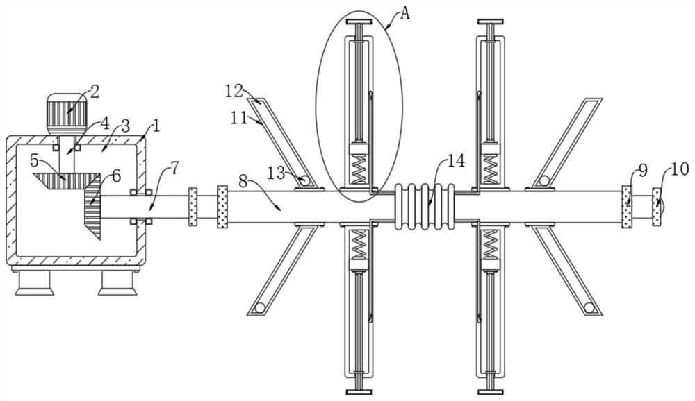
[0025] refer to Figure 1-4 , a pipeline dredging device for smart city construction, comprising a housing 1, a rotating chamber 3 is provided in the housing 1, a motor 2 is installed above the housing 1, and a first rotating rod 4 is vertically provided in the housing 1 , the end of the output shaft of the motor 2 extends into the rotating cavity 3, and is fixedly connected with the upper end of the first rotating rod 4, and the lower end of the first rotating rod 4 is fixedly connected with an incomplete bevel gear 5;

[0026] The trigger mechanism, the trigger mechanism includes the second rotating rod 7 horizontally arranged in the rotating chamber 3, the left end of the second rotating rod 7 is fixedly connected with the first bevel gear 6 matched with the incomplete bevel gear 5, when the incomplete bevel gear 5 meshes with the first bevel gear 6, the incomplete bevel gear 5 drives the first bevel gear 6 to rotate, and when the incomplete bevel gear 5 does not mesh with ...

Embodiment 2

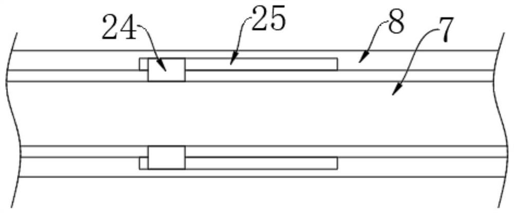
[0034] refer to Figure 5 The difference between this embodiment and Embodiment 1 is that a slide plate 27 is horizontally provided in the rotating cavity 3, and the sliding plate 27 is slidably connected with the inner wall of the rotating cavity 3, and the sliding plate 27 is connected to the inner bottom of the rotating cavity 3 through two second springs. 28 is elastically connected, and the part of the second rotating rod 7 located in the rotating cavity 3 is fixedly connected with a cam 26 matched with the slide plate 27, and under the elastic action of the two second springs 28, the slide plate 27 is offset against the cam 26, that is, When the second rotating rod 7 rotates, it will drive the slide plate 27 to move up and down. The second rotating rod 7 is provided with a liquid outlet pipe 30. The left end of the liquid outlet pipe 30 communicates with the rotating chamber 3, and the sleeve 8 on the left side is set An annular hollow plate 31 is provided, the outer inn...


PUM


Abstract

The invention discloses a pipeline dredging device for smart city construction. The pipeline dredging device comprises a shell and a triggering mechanism, a rotating cavity is formed in the shell, a motor is installed above the shell, a first rotating rod is vertically arranged in the shell, the tail end of an output shaft of the motor extends into the rotating cavity and is fixedly connected withthe upper end of the first rotating rod, the lower end of the first rotating rod is fixedly connected with an incomplete bevel gear, the triggering mechanism comprises a second rotating rod horizontally arranged in the rotating cavity, and the left end of the second rotating rod is fixedly connected with a first bevel gear matched with the incomplete bevel gear. According to the device, only themotor which is high-power device is needed, first hollow plates are driven by centrifugal force generated when the motor rotates to remove sludge on the inner wall of a pipeline, the multiple first hollow plates are driven to move left and right, the sludge removing effect is improved, air is sprayed to the sludge through the multiple air holes in the first hollow plates, and the sludge removing effect is better.

Description

technical field [0001] The invention relates to the field of pipeline dredging, in particular to a pipeline dredging device for smart city construction. Background technique [0002] Pipeline dredging is to dredge the pipeline, clean the silt in the pipeline, and keep it open for a long time to prevent urban waterlogging. Pipeline dredging is an important task that cannot be ignored by the drainage department. For pipeline dredging, there are the following problems : [0003] At present, most of the municipal sewer pipes are manually excavated, which is labor-intensive, and some pipelines are difficult to excavate manually after the silt is deposited, and the efficiency of manual excavation is relatively low. Traditional dredging devices use a variety of high-power devices. , the operation is cumbersome and consumes electric energy, and the existing dredging device cannot be used for pipes with different diameters. These issues are what we need to consider. Contents of t...

Claims


Application Information

Patent Timeline
Patent Type & Authority Applications(China)
IPC IPC(8): E03F9/00
CPCE03F9/005
Inventor 刘庆文
Owner WEIFANG BOTAI ENERGY TECH CO LTD
Why Eureka
Try Eureka