
Multi-parallel control valve mechanism and medical equipment

A technology for controlling valves and valve casings, which is applied in the field of medical equipment, can solve the problems of needing lubrication, large wear, multiple control valves and complex structures, and achieves the effect of convenient processing and simple structure

Active Publication Date: 2021-02-02
HUNAN MICOME ZHONGJIN MEDICAL SCI & TECH DEV CO LTD
View PDF10 Cites 2 Cited by
  • Summary
  • Abstract
  • Description
  • Claims
  • Application Information

AI Technical Summary

Problems solved by technology

[0004] The purpose of the present invention is to provide a multi-parallel control valve mechanism to solve the problems in the prior art that the multi-parallel control valve structure is relatively complex, wears relatively large and needs to be lubricated during work; in addition, the present invention also provides a The medical device with multiple and controlled valve mechanism

Method used


Image

  • Multi-parallel control valve mechanism and medical equipment
  • Multi-parallel control valve mechanism and medical equipment
  • Multi-parallel control valve mechanism and medical equipment

Examples


Embodiment Construction

[0024] Unless otherwise defined, all technical and scientific terms used herein have the same meaning as commonly understood by those skilled in the technical field of the present invention; the terms used in the specification herein are only for the purpose of describing specific embodiments, and are not intended to To limit the invention, for example, the terms "length", "width", "upper", "lower", "left", "right", "front", "rear", "vertical", "horizontal", "top ", "bottom", "inner", "outer" and other indicated orientations or positions are based on the orientations or positions shown in the drawings, which are only for convenience of description and cannot be understood as limitations on the technical solution.

[0025] The terms "include" and "have" in the specification and claims of the present invention and the description of the above drawings, as well as any variations thereof, are intended to cover a non-exclusive inclusion; The terms "first", "second", etc. are used t...


PUM


Abstract

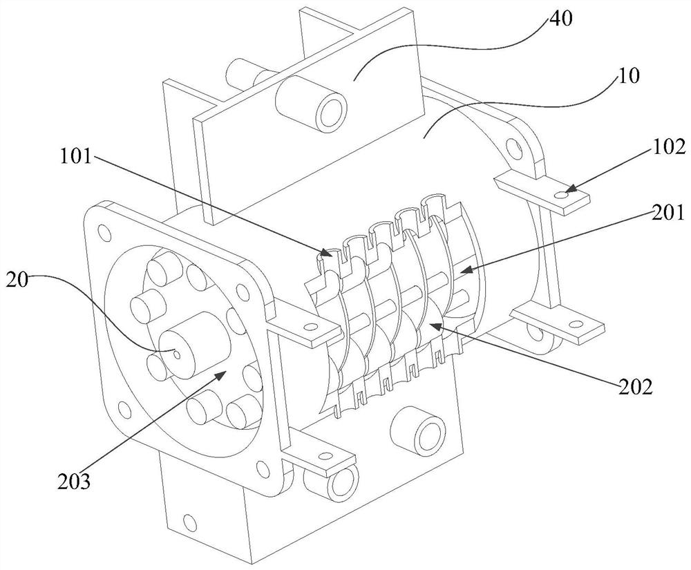
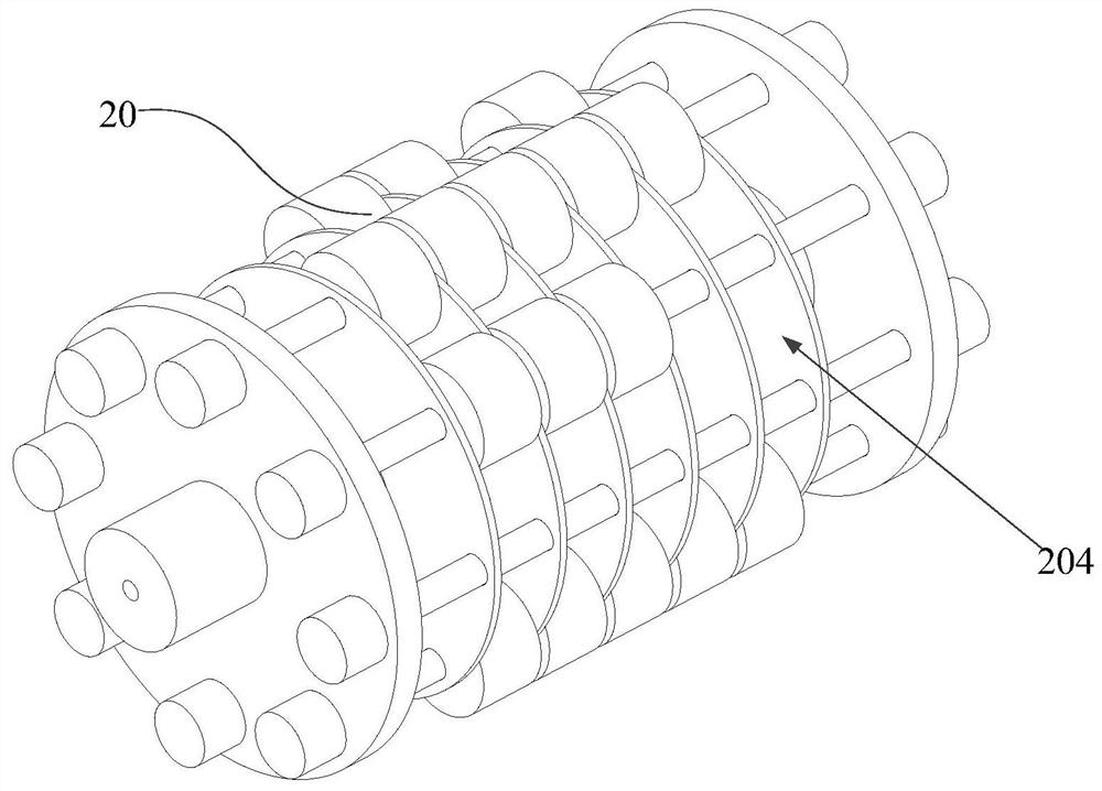
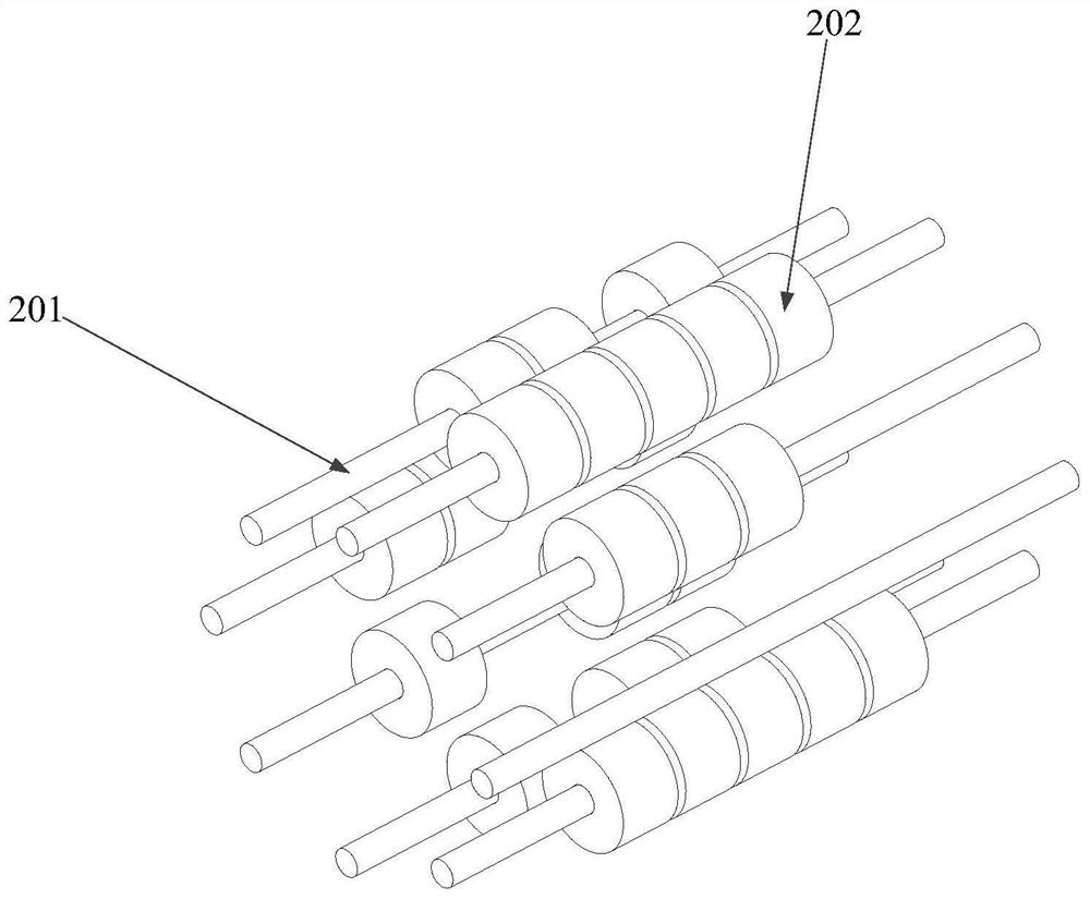
The invention is suitable for the technical field of medical instruments, and relates to a multi-parallel control valve mechanism. The multi-parallel control valve mechanism comprises a valve shell and a valve core; the valve core is arranged in the valve shell, and the portion, on one side of the valve core in the extending direction, of the upper part of the valve shell is hollow; the valve corecomprises a plurality of roller pins, a plurality of rollers and two fixing plates, the two ends of the roller pins are each fixed by one fixing plate, and the roller pins are sleeved with the rollers; and a plurality of hoses are placed on the valve shell, a motor drives the rollers in the valve core to rotate, and the hoses are controlled to be opened or closed according to the condition that whether the rollers extrude the hoses or not. The valve core is composed of the rollers and the roller pins, the structure is simple, and machining is convenient; and the rollers and the hoses are in direct contact and are in rolling friction, so that a push rod and a springback device are not needed, abrasion and lubrication in the movement process do not need to be considered, time and labor aresaved, and high efficiency and reliability are achieved.

Description

technical field [0001] The invention belongs to the technical field of medical equipment, and in particular relates to a multi-parallel control valve mechanism and medical equipment. Background technique [0002] The main components of the current multi-parallel control valve include special-shaped cams, push rods and fixed splints. Among them, the multiple and special-shaped cams are formed by merging multiple cams, and are often formed by integral processing of multiple cams. The number of push rods is related to the number of controlled air pipes, and the fixed splint is used to fix the air pipes. Multiple parallel cams include high pair and low pair. Through the rotation of the cam group, each push rod is in contact with the high pair and the low pair respectively. The principle is that when the push rod contacts the high pair of the cam group, the contact between the push rod and the fixed plate The gap becomes smaller, thereby squeezing the hose to block it, and the p...

Claims


Application Information

Patent Timeline
Patent Type & Authority Applications(China)
IPC IPC(8): F16K7/06F16K31/04F16N1/00
CPCF16K7/06F16K31/04F16N1/00
Inventor 陈文戴征
Owner HUNAN MICOME ZHONGJIN MEDICAL SCI & TECH DEV CO LTD
Learn More