Combustion spreading test device and test method thereof
A test device and test piece technology, which can be used in chemical analysis using combustion, aircraft component testing, etc., and can solve problems such as low versatility
- Summary
- Abstract
- Description
- Claims
- Application Information
AI Technical Summary
Problems solved by technology
Method used
Image
Examples
Embodiment 1
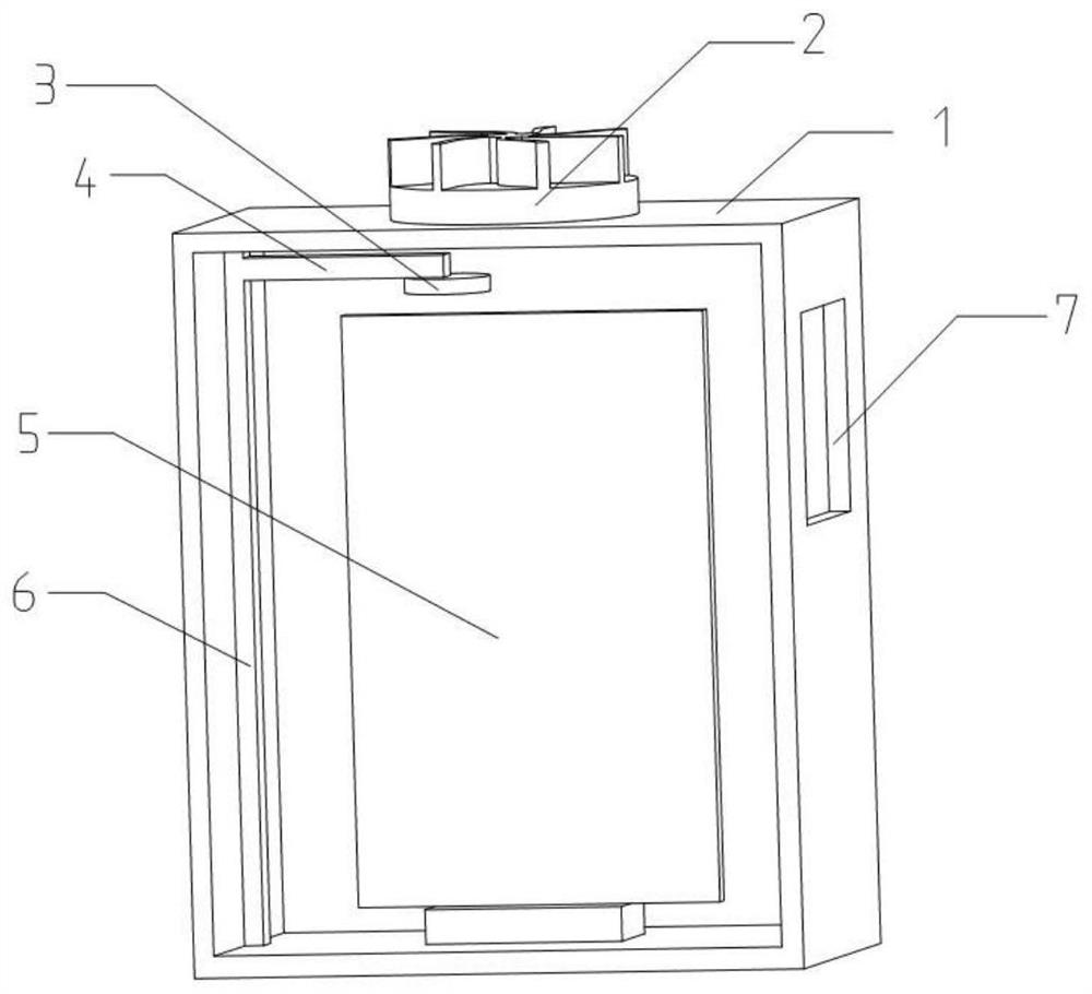
[0039] The embodiment is basically as attached figure 1 As shown: the combustion spread test device in this scheme includes a box body 1 with a cuboid structure with an open front end, and a sample door for closing the box body 1 is provided at the front end of the box body 1; Insulated sample holder.
[0040] An exhaust fan 2 for exhaust and air circulation is installed on the top of the box body 1 . A strip burner that can be used to ignite the test piece and ignite the radiant panel 5 is installed at the bottom of the box body 1 . The left and right sides of the box body 1 are provided with rectangular viewing windows 7, and the viewing windows 7 are provided with high temperature resistant transparent materials. Through the window 7, the burning, spreading and dense smoke in the box body 1 can be visually seen, which is convenient for the test personnel to observe and record in time.
[0041] The radiant plate 5 is located above the strip burner, and the length of the r...
Embodiment 2
[0060] In this embodiment, the radiation plate 5 includes a plurality of heating units arranged in a matrix, and each heating unit works independently. Each heating unit is connected with a control box installed outside the box body 1, and the operation of the heating unit is controlled through the control box. The radiant plate 5 is composed of a plurality of independently working heating units arranged in a matrix, so that it is convenient to conduct local heat radiation tests on the test piece in sections from top to bottom or from left to right when necessary.
Embodiment 3
[0062] In this embodiment, the inner wall of the box body 1 is installed with inwardly inflatable special-shaped obstacles; the special-shaped obstacles include a flame-retardant film formed into a capsule and uniformly covered on the inner wall of the box body 1, and the fire-retardant film communicates with a protruding The connecting pipe of the box body 1 is equipped with a hydraulic pump, and the hydraulic pump is connected with a flame-retardant tank containing a flame-retardant liquid. The hydraulic pump can fill the flame-retardant liquid in the flame-retardant tank into the bag formed by the flame-retardant film. In the object, a special-shaped obstacle protruding toward the inside of the box 1 is formed to simulate the relative position of other cabin facilities adjacent to the test piece in the concealed combustion area, so that the situation during the test can be simulated more realistically and the test results are more accurate. The flame retardant film is a film...
PUM
 Abstract
Description
Claims
Application Information
 - R&D
- Intellectual Property
- Life Sciences
- Materials
- Tech Scout
- Unparalleled Data Quality
- Higher Quality Content
- 60% Fewer Hallucinations
Browse by: Latest US Patents, China's latest patents, Technical Efficacy Thesaurus, Application Domain, Technology Topic, Popular Technical Reports.
© 2025 PatSnap. All rights reserved.Legal|Privacy policy|Modern Slavery Act Transparency Statement|Sitemap|About US| Contact US: help@patsnap.com

