Reference clock loss detection circuit and detection method

A reference clock and loss detection technology, which is applied in the field of integrated circuits, can solve problems such as difficult integration, many circuit units, and complex structure, and achieve the effects of small occupied area, simple circuit structure, and low power consumption

Active Publication Date: 2021-02-02
CHENGDU SINO MICROELECTRONICS TECH CO LTD
View PDF19 Cites 3 Cited by
  • Summary
  • Abstract
  • Description
  • Claims
  • Application Information

AI Technical Summary

Problems solved by technology

[0007] Although the patent application 3 does not rely on an additional counting reference clock, there are many units in the circuit and the structure is very complicated, so it is not easy to integrate

Method used


Image

  • Reference clock loss detection circuit and detection method
  • Reference clock loss detection circuit and detection method
  • Reference clock loss detection circuit and detection method

Examples


Embodiment Construction

[0034] Specific embodiments of the present invention will be described in detail below in conjunction with the accompanying drawings.

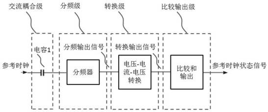
[0035] A reference clock loss detection circuit, such as figure 1 As shown, the circuit is divided into 4 stages: including the AC coupling stage circuit, frequency division stage circuit, conversion stage circuit and comparison output stage circuit connected in sequence, the reference clock input AC coupling stage circuit, and the AC coupling stage circuit plays the role of isolating DC ; The frequency division stage circuit organizes the duty cycle of the reference clock and adjusts the signal amplitude of the reference clock, and outputs the frequency division output signal to the conversion stage circuit; the conversion stage circuit converts the frequency division output signal output by the frequency division stage circuit into a conversion output signal , input to the comparison output stage circuit; the comparison output stage circuit ...


PUM


Abstract

The invention belongs to the field of integrated circuit design, and provides a reference clock loss detection circuit, which comprises an alternating current coupling capacitor, a frequency divider,a voltage, current and voltage converter, a comparator and an output buffer, wherein thealternating current coupling capacitorseparates a direct current signal of the reference clock, the frequency divider sorts the duty ratio of a reference clock and adjusts the signal amplitude of the reference clock, the signal after frequency division passes through the voltage-current converter, a hopping clock signal and a non-hopping logic low signal can be distinguished, the comparator and the output buffer output a reference clock state signal, and when the reference clock to be detected is normal, lost and other abnormities happen, a signal is outputted to represent the state of the reference clock so as to realize detection of the state of the reference clock.

Description

technical field [0001] The invention belongs to the technical field of integrated circuits, and in particular relates to a circuit for detecting the state of a reference clock. Background technique [0002] In a computer or communication system, the clock circuit is a very important part of the system. The loss or abnormality of the external clock of the chip will affect the normal operation of the chip, so it is necessary to design a special circuit for clock detection. [0003] The clock detection circuit can adopt the counter mode, such as in patent 1 (application number: 99127039.8, authorized announcement number: CN 1148874C, patent name: a kind of clock signal pulse loss detection circuit), using multiple flip-flops, multiple inverters , an AND gate, a built-in counter and a comparator, the circuit simultaneously receives the external detected clock signal a and the extra counting clock signal b, and the built-in counter also receives the enable signal from the outside...

Claims


Application Information

Patent Timeline
Patent Type & Authority Applications(China)
IPC IPC(8): G01R31/317
CPCG01R31/31727G01R31/31726G01R31/31703Y02B70/10
Inventor 湛伟马淑彬丛伟林
Owner CHENGDU SINO MICROELECTRONICS TECH CO LTD
Why Eureka
Try Eureka