
LED display backboard detection device and detection method thereof

A technology for displaying backplanes and detection devices, which is applied in the direction of semiconductor/solid-state device testing/measurement, electrical components, circuits, etc., can solve the problems of low backplane defect detection rate and complicated backplane detection process, and achieves improved efficiency and accuracy. efficiency, easy to move, low cost of use

Active Publication Date: 2021-02-02
SHENZHEN CHINA STAR OPTOELECTRONICS SEMICON DISPLAY TECH CO LTD
View PDF5 Cites 4 Cited by
  • Summary
  • Abstract
  • Description
  • Claims
  • Application Information

AI Technical Summary

Problems solved by technology

[0006]In order to overcome the traditional display backplane detection method in the prior art, it is usually determined whether the missing has an impact on the lighting after personnel research and judgment. The backplane detection process is complicated, and the backplane Due to the technical problem of low board defect detection rate, the embodiment of the present application provides an LED display backplane detection device and its detection method

Method used


Image

  • LED display backboard detection device and detection method thereof
  • LED display backboard detection device and detection method thereof

Examples


Embodiment Construction

[0030] The technical solutions in the embodiments of the present application will be clearly and completely described below in conjunction with the drawings in the embodiments of the present application. Apparently, the described embodiments are only some of the embodiments of this application, not all of them. Based on the embodiments in this application, all other embodiments obtained by those skilled in the art without making creative efforts belong to the scope of protection of this application.

[0031] In the description of the present application, it should be understood that the terms "center", "longitudinal", "transverse", "length", "width", "thickness", "upper", "lower", "front", " Orientation indicated by rear, left, right, vertical, horizontal, top, bottom, inside, outside, clockwise, counterclockwise, etc. The positional relationship is based on the orientation or positional relationship shown in the drawings, which is only for the convenience of describing the a...


PUM


Abstract

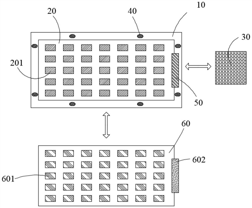
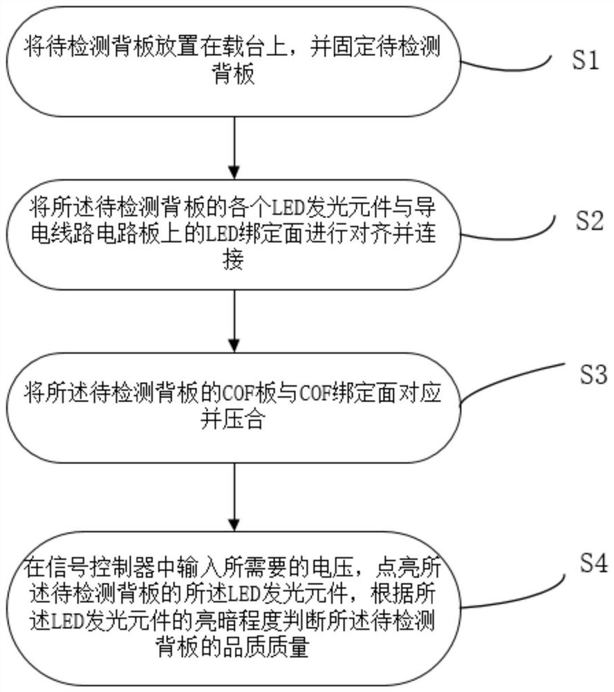
The invention discloses an LED display backboard detection device, which comprises: a carrying platform, a conductive circuit board and LED binding surfaces, wherein the conductive circuit board comprises a plurality of LED binding surfaces, each LED binding surface is connected with a conductive circuit in the conductive circuit board, and each LED binding surface is connected with LED light-emitting elements on to-be-detected backboard in a one-to-one correspondence manner; and a signal controller used for providing voltage for the conductive circuit board. According to the invention, the conductive circuit board transmits voltage to each LED light-emitting element on the to-be-detected backboard and lightens each LED light-emitting element, and the quality of the corresponding positionof the to-be-detected backboard is judged according to the brightness degree of each LED light-emitting element.

Description

technical field [0001] The present application relates to the technical field of displays, in particular to an LED display backplane detection device and a detection method thereof. Background technique [0002] Micro light emitting diode (Micro light emitting diode, referred to as Micro-LED) usually refers to reducing the size of the LED chip to a size within 200 microns on the basis of the traditional LED chip structure, and the red, green, and blue three-color Micro LED according to a certain Regularly arranged on thin film transistors (Thin Film Transistor, TFT for short) or complementary metal oxide semiconductors (Complementary Metal Oxide Semiconductor, COMS for short), form a micro-device capable of realizing full-color display. This kind of display has independently controlled display pixels, and has the characteristics of independent light-emitting control, high brightness, low power consumption, ultra-high resolution and ultra-high color saturation, and the Micro-...

Claims


Application Information

Patent Timeline
Patent Type & Authority Applications(China)
IPC IPC(8): H01L21/66
CPCH01L22/14H01L22/12
Inventor 王明耀刘俊领
Owner SHENZHEN CHINA STAR OPTOELECTRONICS SEMICON DISPLAY TECH CO LTD
Learn More