Supercharge Your Innovation With Domain-Expert AI Agents!

Display panel, manufacturing method thereof, and display device

A technology for display panels and substrates, used in semiconductor/solid-state device manufacturing, semiconductor devices, electrical components, etc., can solve problems such as uneven brightness of the screen, reduced luminous efficiency, and different losses, and achieve improved brightness uniformity and color reduction. degree of deviation, the effect of reducing leakage current

Active Publication Date: 2022-05-03
WUHAN CHINA STAR OPTOELECTRONICS SEMICON DISPLAY TECH CO LTD
View PDF5 Cites 0 Cited by
  • Summary
  • Abstract
  • Description
  • Claims
  • Application Information

AI Technical Summary

Problems solved by technology

[0003] With the gradual development and maturity of OLED technology, customers have higher and higher requirements for OLED display panels. For example, the brightness uniformity of low gray scale is required to reach more than 80%, and the chromaticity shift is within 4 JNCD (Just Noticeable Color Difference, The standard for measuring the color accuracy of the screen), but due to the horizontal leakage current between adjacent pixels of the display panel at low grayscale, and between the common functional layers of the OLED device, resulting in a pixel that should not emit light Slight luminescence, resulting in color cast and uneven brightness at low gray levels
Another reason is that the OLED device is formed in the pixel hole formed by the pixel definition layer. When the light is emitted from the hole, it will be absorbed and refracted by the side wall and lost, resulting in a decrease in luminous efficiency. It is especially obvious in the gray scale. Since the driving current is small in the low gray scale, the luminous flux emitted by the OLED is small, and the amount of light absorbed by the side wall of each pixel hole is also different, so the loss is also different, resulting in the amount of light that finally reaches the human eye. There are also differences, which eventually lead to uneven brightness of the picture

Method used


Image

  • Display panel, manufacturing method thereof, and display device
  • Display panel, manufacturing method thereof, and display device
  • Display panel, manufacturing method thereof, and display device

Examples


Embodiment Construction

[0026] The following will clearly and completely describe the technical solutions in the embodiments of the present invention with reference to the accompanying drawings in the embodiments of the present invention. Obviously, the described embodiments are only some, not all, embodiments of the present invention. Based on the embodiments of the present invention, all other embodiments obtained by those skilled in the art without making creative efforts belong to the protection scope of the present invention.

[0027] In describing the present invention, it should be understood that the terms "center", "longitudinal", "transverse", "length", "width", "thickness", "upper", "lower", "front", " The orientation or positional relationship indicated by "rear", "left", "right", "vertical", "horizontal", "top", "bottom", "inner", "outer", etc. is based on the orientation shown in the drawings Or positional relationship is only for the convenience of describing the present invention and ...


PUM

PropertyMeasurementUnit
depthaaaaaaaaaa
thicknessaaaaaaaaaa
widthaaaaaaaaaa

Abstract

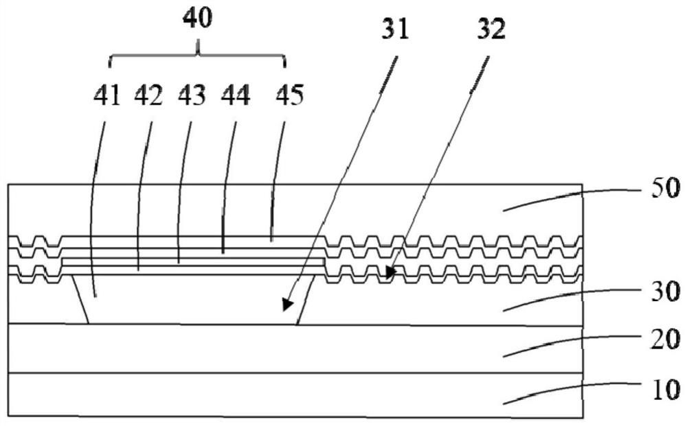
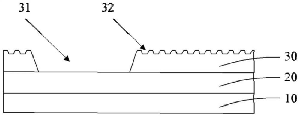
The present application discloses a display panel, a manufacturing method thereof, and a display device. The display panel includes: a substrate; an array functional layer configured on the substrate; a pixel definition layer configured on the array functional layer, including forming A plurality of through holes arranged in an array in the pixel area, and in the non-pixel area, the surface of the pixel definition layer includes a plurality of grooves distributed on the entire surface; and the OLED device layer includes a common function layer, and the common function A layer is conformally formed on the pixel definition layer. By setting the groove, in the OLED device layer on the pixel definition layer, the conduction path of the common functional layer between adjacent pixels is extended, which is equivalent to increasing the resistance, so that the leakage current between adjacent pixels is reduced. Small, it can effectively prevent the phenomenon of "stealing pixels".

Description

technical field [0001] The present application relates to the field of display technology, in particular to a display panel, a manufacturing method thereof, and a display device. Background technique [0002] OLED (Organic Light-Emitting Diode, Organic Light-Emitting Diode) display technology, because of its characteristics of self-illumination, wide viewing angle, high contrast, low power consumption, high response speed, and can be applied to flexible display, has become the most Sought after display type. [0003] With the gradual development and maturity of OLED technology, customers have higher and higher requirements for OLED display panels. For example, the brightness uniformity of low gray scale is required to reach more than 80%, and the chromaticity shift is within 4 JNCD (Just Noticeable Color Difference, The standard for measuring the color accuracy of the screen) is below), but because the display panel is in low grayscale between adjacent pixels, due to the la...

Claims


Application Information

Patent Timeline
Patent Type & Authority Patents(China)
IPC IPC(8): H01L27/32H01L51/56
CPCH10K59/122H10K59/1201H10K71/00
Inventor 蔡振飞
Owner WUHAN CHINA STAR OPTOELECTRONICS SEMICON DISPLAY TECH CO LTD
Features
  • R&D
  • Intellectual Property
  • Life Sciences
  • Materials
  • Tech Scout
  • Unparalleled Data Quality
  • Higher Quality Content
  • 60% Fewer Hallucinations
Learn More