Connection coupling

A technology for connecting couplings and auxiliary devices, which is applied in the field of connecting coupling devices for hoses, can solve problems such as cost, and achieve the effect of anti-torsion

Active Publication Date: 2021-02-02
NEOPERL
View PDF10 Cites 0 Cited by
  • Summary
  • Abstract
  • Description
  • Claims
  • Application Information

AI Technical Summary

Problems solved by technology

However, the production of such contours is often time-consuming

Method used


Image

  • Connection coupling
  • Connection coupling
  • Connection coupling

Examples


Embodiment Construction

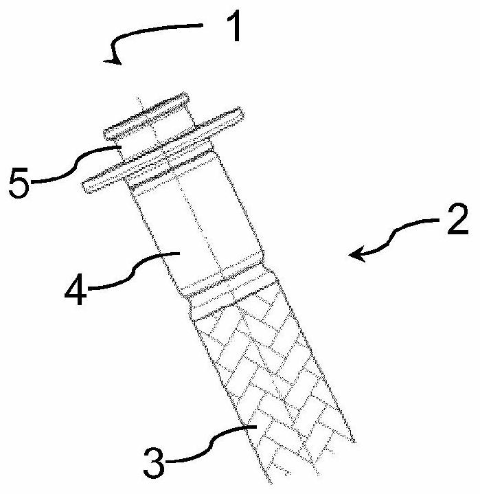
[0092] figure 1 A connection coupling according to the invention, generally designated 1 , is shown, onto which the hose end 2 of the hose 3 is plugged. The hose end 2 is crimped in a manner known per se with a crimping sleeve 4 .

[0093] The connection coupling 1 also has a connection piece 5 with which the hose 3 can be connected to a fitting, to another hose or to another connection point.

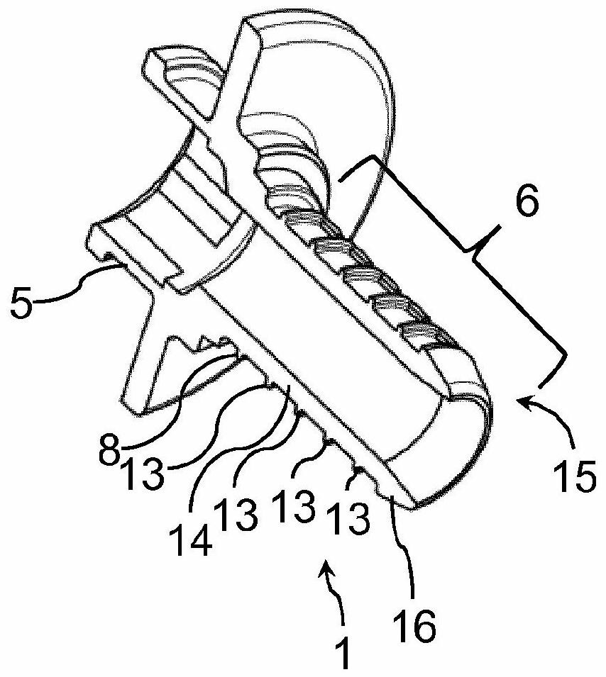
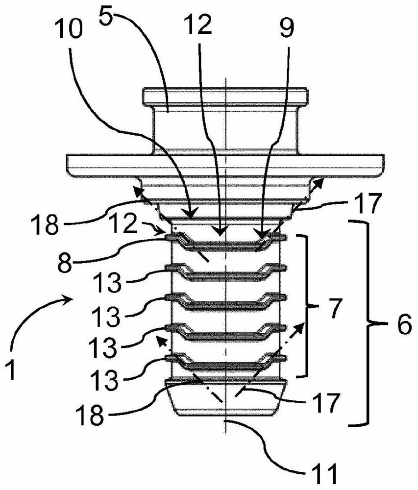
[0094] figure 2 A view cut along an axial plane of the connection coupling device 1 is shown. It can be seen that the connection coupling 1 has a hose connector 6 which is inserted into the hose end 2 for use. A rib structure 7 is formed on the outside of the hose connection 6 (cf. image 3 ). The rib structure 7 serves for stress relief and has at least one rib 8 .

[0095] image 3 and Figure 4 The connection coupling device 1 is shown in two side views rotated relative to each other. by overview image 3 and Figure 4 It can be seen that the rib 8 has a closed circumfer...


PUM


Abstract

The invention relates to a connection coupling (1), wherein at least two rib sections (9, 10) are aligned at an angle to each other at at least one rib (8) of a rib structure (7) of a hose nipple (6)such that the course directions (17, 18) in the rib sections (9, 10) are aligned at an angle to each other.

Description

technical field [0001] The invention relates to a connection coupling for hoses, comprising a hose connector on which a rib structure comprising at least one rib is formed. Background technique [0002] It is known to form ribs on hose connections in order to transmit tensile forces. In order to improve the torsion resistance, it is proposed to form a groove between two ribs, the groove base of which deviates from the rotational symmetry. It is also proposed to produce ribs with a non-circular peripheral contour, ie a peripheral contour that cannot be delineated by a cylindrical wall. However, the production of such contours is often complex. Contents of the invention [0003] The object of the present invention is to provide a rib structure which provides improved torsional resistance. [0004] According to the invention, the features of claim 1 are provided in order to solve the object. In particular, it is therefore provided according to the invention in a coupling ...

Claims


Application Information

Patent Timeline
Patent Type & Authority Applications(China)
IPC IPC(8): F16L33/207
CPCF16L33/2071F16L33/20
Inventor W·库里
Owner NEOPERL
Why Eureka
Try Eureka