
Output material pipe of feeding vehicle

A feeding truck and feeding tube technology, applied in transportation and packaging, loading/unloading, poultry industry, etc., can solve the problems of burning the motor, jamming of the auger, and easy storage of materials in the feeding tube, so as to solve the problem of jamming and eccentricity. problems, facilitate maintenance and replacement, and ensure the effect of assembly tolerances

Pending Publication Date: 2021-02-05
广州市华南畜牧设备有限公司
View PDF1 Cites 0 Cited by
  • Summary
  • Abstract
  • Description
  • Claims
  • Application Information

AI Technical Summary

Problems solved by technology

[0002] At present, the discharge structure of the auger used for the limited feeding of breeders is mostly integrated welding connection between the conveying material pipe and the hopper, or the iron is galvanized and connected to the hopper through screws, so the welding process will cause many problems: first, The tolerance problem of the flange surface of the installed auger motor, the existing welding process cannot realize the verticality tolerance of the assembly flange and the material pipe, and the coaxiality tolerance between the motor shaft and the auger output shaft after the motor is assembled, which is easy to cause The auger is stuck, and the auger is seriously eccentric; secondly, it is difficult to smooth the weld seam with the material tube of the welding process, and these corners have a certain impact on the fluidity of the feed, which makes it easy to store material in the material tube; lastly, in the past The material pipes are all made horizontal, so that the water flow when cleaning the hopper is easy to flow back to the motor end and burn the motor
However, this structure still cannot completely solve the eccentricity problem in actual use, and the bearings and plum blossom couplings in the connecting flange assembly are often damaged and replaced

Method used


Image

  • Output material pipe of feeding vehicle
  • Output material pipe of feeding vehicle
  • Output material pipe of feeding vehicle

Examples


Embodiment Construction

[0030] The technical solutions of the present invention will be further described below in conjunction with the accompanying drawings and through specific implementation methods.

[0031] Wherein, the accompanying drawings are only for illustrative purposes, showing only schematic diagrams, rather than physical drawings, and should not be construed as limitations on this patent; in order to better illustrate the embodiments of the present invention, some parts of the accompanying drawings will be omitted, Enlargement or reduction does not represent the size of the actual product; for those skilled in the art, it is understandable that certain known structures and their descriptions in the drawings may be omitted.

[0032]In the drawings of the embodiments of the present invention, the same or similar symbols correspond to the same or similar components; , "inner", "outer" and other indicated orientations or positional relationships are based on the orientations or positional r...


PUM


Abstract

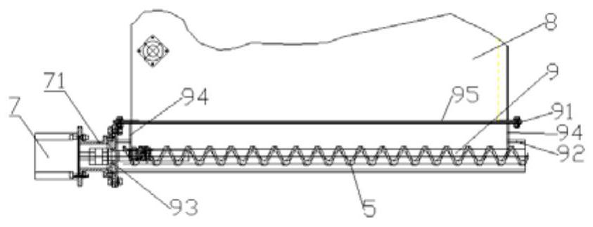
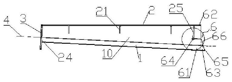
The invention discloses an output material pipe of a feeding vehicle. The output material pipe comprises a material cavity formed through a cavity wall, the material cavity is composed of an auger pipe cavity provided with an auger and a material storage cavity connected with the auger pipe cavity, a tail end opening section of the auger pipe cavity is a discharging opening, and a side platform connected with a hopper in an assembled manner is formed at the top of a side face cavity wall forming the material storage cavity; a pipe cavity center line of the auger pipe cavity inclines downwardsto form an included angle with the platform surface of the side platform; and the discharging opening is provided with an extending section, and the end face of the extending section is an inclined end face inclining downwards. According to the output material pipe, accumulated materials are eliminated, the phenomenon of feed mildewing is avoided, accumulated water is eliminated when the hopper iscleaned, the motor is prevented from being burnt by the accumulated water, the motor does not need to be detached for storage when the material cavity is cleaned, and the problem of feed leakage is solved.

Description

technical field [0001] The invention relates to the technical field of chicken raising equipment in animal husbandry, in particular to a technology of an output material pipe of a feeding vehicle. Background technique [0002] At present, the discharge structure of the auger used for the limited feeding of breeders is mostly integrated welding connection between the conveying material pipe and the hopper, or the iron is galvanized and connected to the hopper through screws, so the welding process will cause many problems: first, The tolerance problem of the flange surface of the installed auger motor, the existing welding process cannot realize the verticality tolerance of the assembly flange and the material pipe, and the coaxiality tolerance between the motor shaft and the auger output shaft after the motor is assembled, which is easy to cause The auger is stuck, and the auger is seriously eccentric; secondly, it is difficult to smooth the weld seam with the material tube ...

Claims


Application Information

Patent Timeline
Patent Type & Authority Applications(China)
IPC IPC(8): A01K39/012A01K39/014B65G65/46
CPCA01K39/0125A01K39/014B65G65/46
Inventor 林先航隆荣奇
Owner 广州市华南畜牧设备有限公司
Learn More